If you’d like to join the discussion of the S-Pixie local oscillator check out Ham Radio Homebrew Projects on reddit.
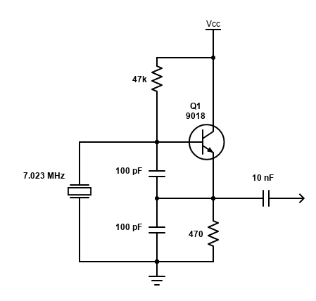
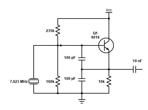
The S-Pixie uses a Colpitts crystal oscillator.
I found a great video by Craig (devttys0 on YouTube) that explains how it works and discusses design considerations.
Local Oscillator Analysis
I’ve been having fun following along with Craig’s video and using his Colpitts crystal oscillator design ideas to evaluate the S-Pixie local oscillator design.
I tried to duplicate the test of the oscillator feedback network that Craig conducts at 5:52 in his video on the S-Pixie circuit with partial success. I was able to observe the change in gain and the flip of phase between the input and output signals but not with the resolution that Craig obtained. This isn’t surprising given I’m using the Analog Discovery 2 as a function generator and I built the test circuit on a breadboard.
One thing I couldn’t duplicate was the gain Craig shows from the output of the feedback network as the input frequency approaches the networks resonance frequency. In my setup the output signal was always less than or equal to the input signal. Again, this may be due to test setup.
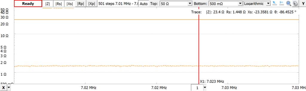
I tried other values for the capacitors in the capacitor divider. This seemed appropriate as the impedance of the specified 100 pF capacitor is about 225 ohms at 7.023 MHz.
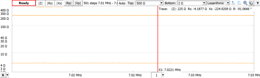
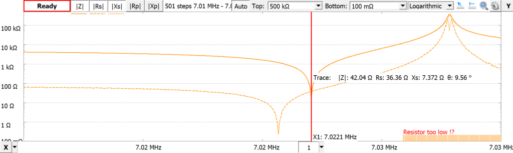
This is substantially higher than the impedance of the crystal, which I measured at 42 ohms at resonance. (I don’t have a datasheet for the S-Pixie 7.023 MHz crystal. For future reference I found some generic 7.023 MHz crystals with a load capacitance of 20 pF).
At this impedance, 1 nF capacitors are appropriate, but using them didn’t have much effect on my results. I was able to increase the gain of the network somewhat, but still not greater than one.
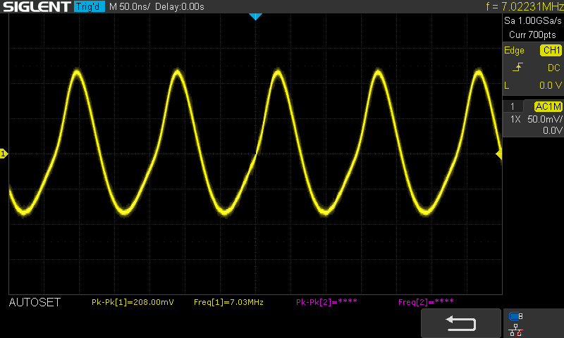
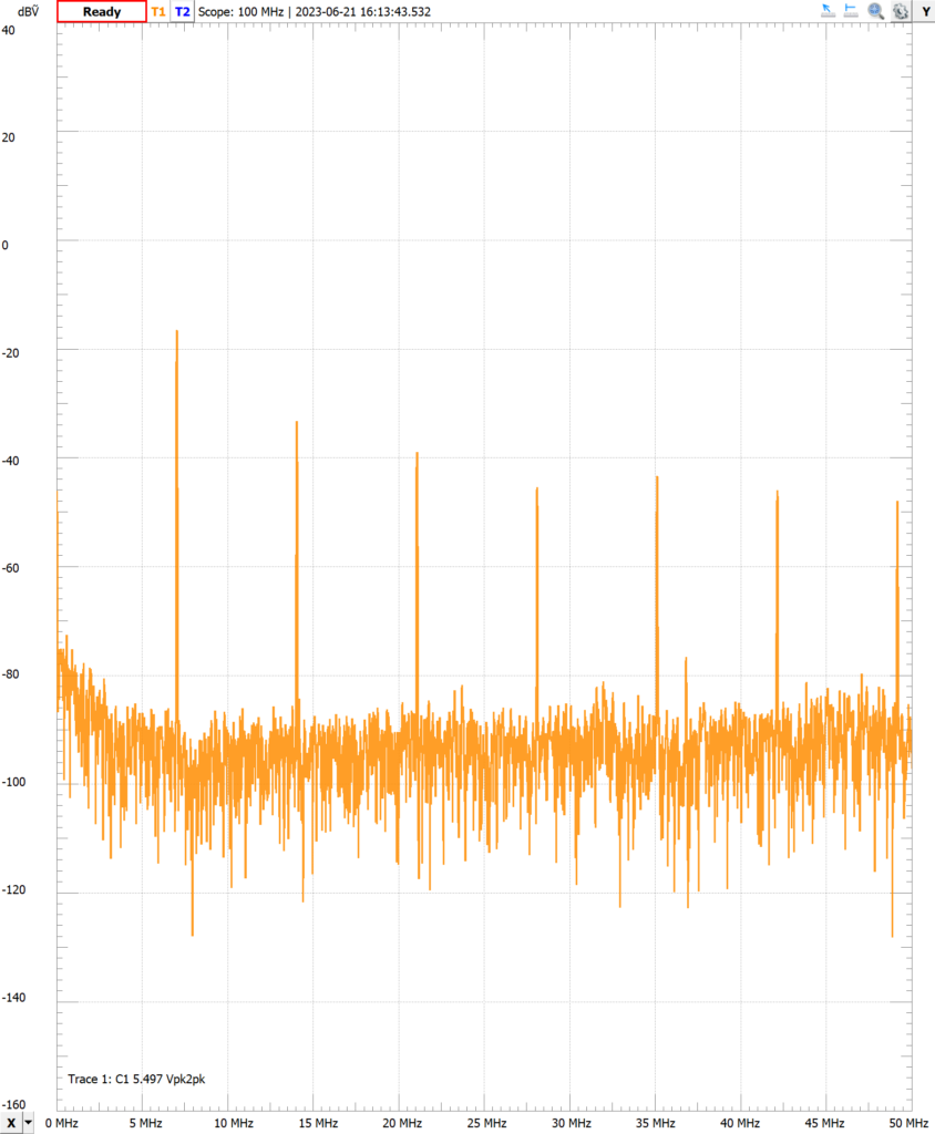
In both my PCB and breadboard builds, I noticed that the base-emitter was reversed biased and the output was distorted, with significant harmonics.
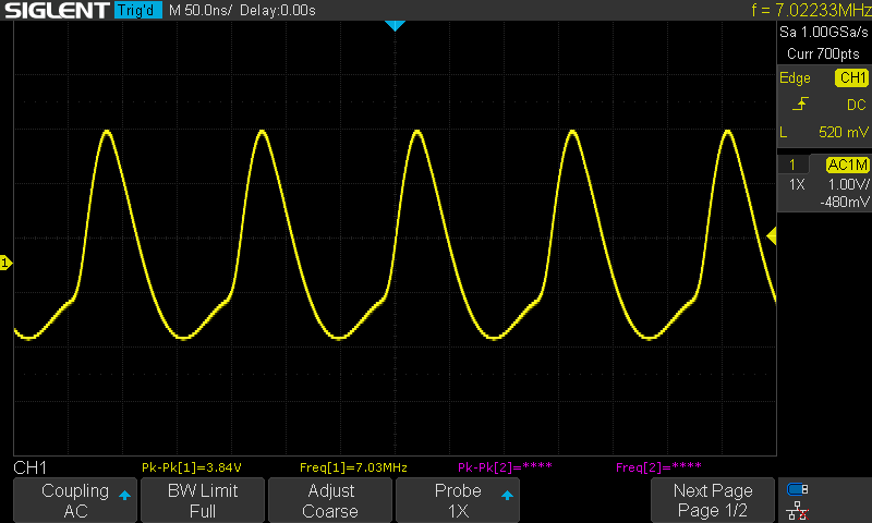
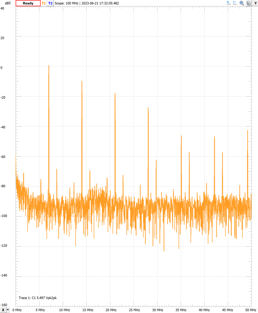
Note that the output for the PCB build local oscillator is more distorted than this but it isn’t useful for comparison here as the local oscillator can’t be easily isolated. I’ll look at it once the breadboard build is more complete. However, regardless of the signal differences, the spectrum is very similar to the breadboard build.
Redesigning the Local Oscillator
To examine this, I tried redesigning the S-Pixie Colpitts crystal oscillator as Craig discusses beginning at 17:11 in his video. I didn’t have much success following Craig’s methodology as every time I modified base resistor divider to properly bias the base-emitter junction, the emitter voltage would rise, maintaining the original reverse bias. I ultimately used trial-and-error to properly bias the transistor.
The extra biasing resistor in this design could be a problem for the S-Pixie. It has almost no extra space available on its PCB. This design resulted in a somewhat better looking output signal.
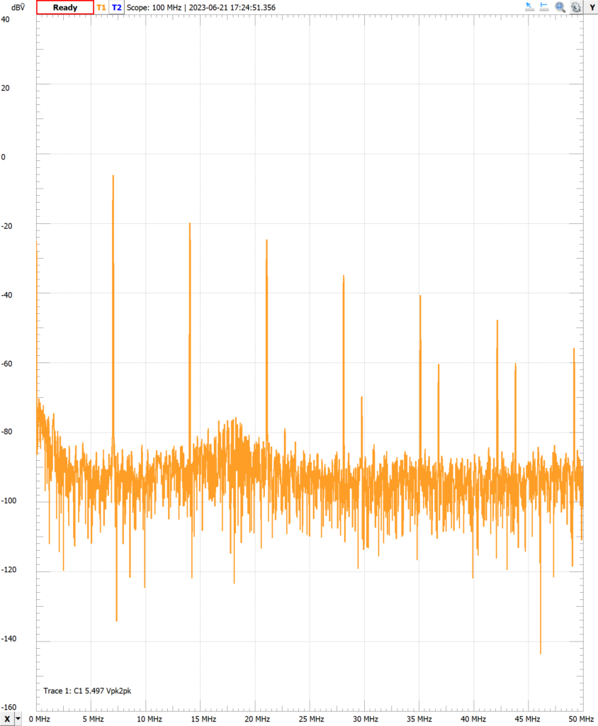
But no improvement in it’s spectrum.
And a likely downside of this redesign is that the local oscillator output signal is reduced by a factor of 20.
Then I found that subtracting the base and emitter voltages as I was originally doing, did not accurately reflect the base-emitter bias. These always reflected the junction as reversed biased (not sure why). However, when I checked the base-emitter voltage directly, I found that the junction was in fact forward biased. I’ll have to go back and make some more measurements.
Local Oscillator Redesign – Part 2
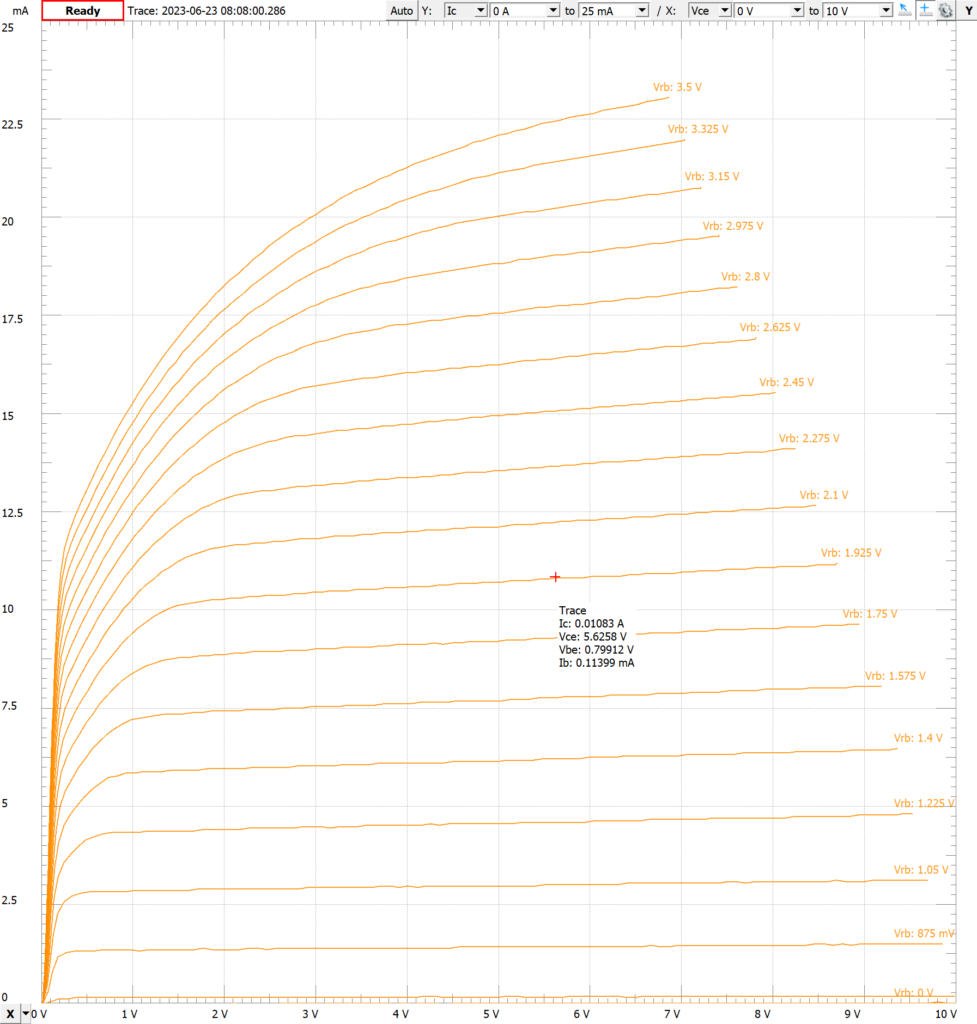
Revisiting Craig’s video at 29:45, I saw that he measures the bias voltages without the crystal installed. Duh. By measuring them with the crystal installed, I was including the AC component from the crystal. Removing the crystal (I had to remove the capacitor divider as well), Q1 (9018 datasheet) in the S-Pixie with a 12 volt power supply is biased as follows:
- Ve = 5.24 V
- Vce = 5.6 V
- Vbe = 0.75 V
- Ib = 106 uA
- Ie = 10.9 mA
This is consistent with the transistor’s characteristic curve from its datasheet as well as one I generated from the Analog Discovery 2.
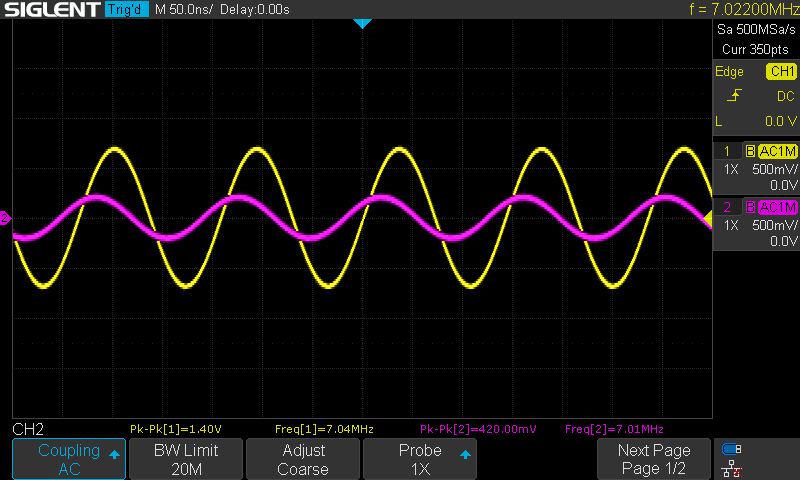
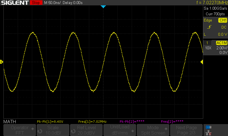
But how is the feedback network driving the base of the transistor? Using the method discussed by Craig at 30:57 in his video, I measured the crystal input sine wave at 8.4 volts peak-to-peak.
I didn’t calculate the AC load line but it isn’t hard to visualize that with this biasing and feedback signal level, the S-Pixie is operating in at least partially regions that aren’t particularly linear. With this knowledge I can revisit my redesign to see if I can get a more linear response from the local oscillator.
I tried adjusting the values of the base resistor divider and emitter resistors to move the DC operating point so that the collector current was about 5 mA. This only resulted in a slight improvement in the oscillator output signal.
I also examined reducing the feedback signal level by adjusting the emitter voltage by changing the values of the capacitors in the capacitor divider as discussed by Craig at 33:26 in his video (Craig actually increases the emitter voltage but you can decrease it by increasing the value of C2). This didn’t provide much improvement by itself. Apparently I couldn’t reduce the feedback enough to keep the transistor within its active region. I did notice though I got a much more sinusoidal signal by removing C2 and increasing C1 (to 1 nF for example). It still had significant harmonics though.
Obviously I needed a different method to reduce the feedback. That will be the subject of my next post.