In the S-Pixie, the portion of the circuit including Q2 (8050 datasheet) serves dual purposes. It’s a mixer when receiving and a power amplifier when transmitting. Here is the relevant portion of the mixer circuit.

When transmitting, the 10k resistor is shorted out by the CW key (not shown in the schematic above), biasing the transistor to operate as a power amplifier.
I haven’t found a good explanation of how the transistor does the mixing in this particular circuit. The mathematical “magic” of mixing is covered in chapter 12, page 12.26 of the ARRL Handbook (100th edition) . A few good YouTube videos, here and here, cover it as well.
Building and Testing the Circuit
This was an easy addition to my breadboard build, but I wasn’t sure of the appropriate signal to feed this for testing. Obviously, I wanted something around 7.023 MHz, but at what voltage level. I think I read somewhere that antenna signals can be in the micro-volt range.
I first verified that my function generator could produce harmonic free, fractional megahertz signals after some earlier mixer tests showed lots of harmonics in the output.

No problem at those frequencies.
I hooked up my function generator at 7.023 MHz and slowly increased the signal voltage. It took a bit of fiddling with my oscilloscope to tease a signal out of the noise. I couldn’t see anything but noise below an input of about 5 mV and at that level there was barely a wobble in the overall noise level.
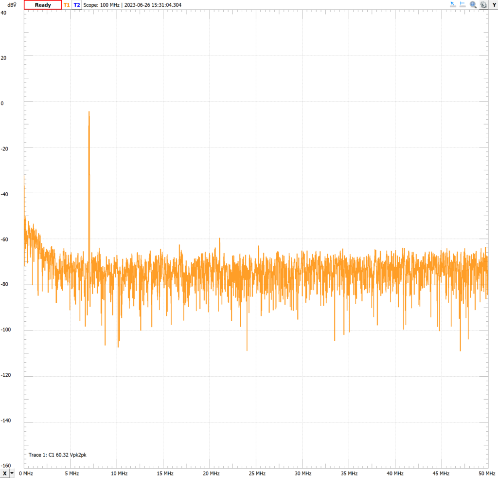
With a bit of trial and error, for my tests I ultimately feed the mixer circuit with a 7.025 MHz, 200 mV RF signal from the antenna side of the Pi filter. Because of the bandwidth limit of my Analog Discovery 2 function generator, this yielded about a 320 mV P-P signal to the input of the Pi filter. Here’s the output from the mixer circuit.
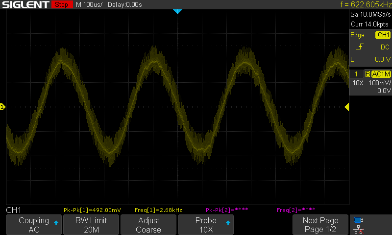
The approximately 2.7 kHz signal has over 100 mV of high frequency noise and that’s with my oscilloscope’s bandwidth limit enabled, which attenuates frequencies above 20 MHz. The noise level is about triple that without this enabled.
With this signal level, I was able to hear a tone with a crystal earpiece connected to the mixer output. Adjusting the input frequency up or down, increased or decreased the audio output frequency as expected. Between 7.022 MHz and 7.023 MHz there was no detectable audio output from the earpiece, though the scope indicated a signal frequency of about 300-600 Hz. Perhaps my age is showing as I’m guessing someone younger could hear that audio signal. As expected the signal was audible again at 7.021 MHz. Adjusting the frequency on my function generator isn’t particularly easy but I manually adjusted the frequency to non-zero hundreds and tens of Hz and could hear the change in frequency in the earpiece. That type of fine tuning is tedious though. I didn’t even try detecting changes in the ones place.
This got me to thinking. If the S-Pixie transmits and received at 7.023 MHz, how is a received signal heard, at least by someone without perfect hearing? Wouldn’t the mixer output, ideally be 0 Hz. Even considering crystal variation, my crystal is actually resonant at about 7.0221 MHz, the audio signal from the mixer would be at a frequency too low for many people. (Note that I’m not considering here the S-Pixie feature that provides some frequency flexibility). I think that question will have to wait until I dive into the transmitter.
Further testing of the S-Pixie mixer
I wanted to do a bit more controlled testing of the S-Pixie mixer, so I isolated it from the rest of the circuit and fed it a 7.023 MHz signal in place of the local oscillator and a 7.025 MHz signal as the RF signal (I needed to set these at 2 volts to get any output, 1 volt was insufficient).
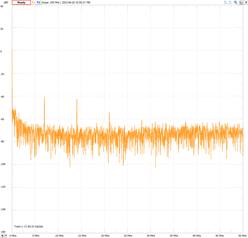
Checking the frequency spectrum of the output I noticed harmonics at every multiple of 7 MHz. This surprised me. I expected a response at 7 and 14 MHz, but not higher. Thinking this was due to a limitation of the Analog Discovery 2, I tested again with my oscilloscope and got the same result.
I thought perhaps the high frequencies and breadboard build might be causing the higher harmonics so I built another mixer circuit and fed it much lower frequency signals. I got a similar result, harmonics at multiples of the input frequencies and if these differed by much, harmonics of the difference as well.
Now for ease of testing I was using my Analog Discovery 2, making the signal and scope connections with flywires. Thinking I had some bad connections, I swapped these for probes using the BNC Adapter. Bingo, the harmonics mostly disappeared (note that the image below is at the output of the mixer, after capacitor C9 which filters, somewhat, higher frequency components).
Reviewing my Extra licensing exam study material ( The ARRL Extra Class License Manual, pg. 6-19), I see that we do expect higher order harmonics from the mixer. From my very basic testing, it seems that a transistor in this setup has some mixing ability almost regardless of it’s bias. I suppose it’s a question of efficiency, but definitely worth more testing. Someday.
The response at 2 kHz wasn’t visible in the frequency spectrum plot at this resolution. A capture in the audio frequency range showed a predominant peak at 2 kHz and lower magnitude harmonics above that.

Examining the signal on the oscilloscope, I got, as expected, a 2 kHz signal at the output of the mixer circuit.

Interestingly, this signal was very clean, apparently without the high frequency components seen in my original tests. Since the input signals are clean, the difference must be due to the local oscillator, which was removed for this test.
Further testing the audio capabilities of this circuit, I was able to drive an 8 ohm speaker with this mixer circuit (that is, without the Pixie audio amplifier). And while I wasn’t able to get an oscilloscope trace of the output (other than a slight wobble in the noise level) with 1 volt input signals, I was able to hear a response from the speaker. The input level of the local oscillator was most important. With the local oscillator at 1 volt, I was able to just detect an audio output from the mixer with the RF signal at 100 mV. With the local oscillator at 2 volts, I was able to just detect an audio output from the mixer with the RF signal at 10 mV. These signals were not discernable from noise on the oscilloscope. This likely has some implications for the S-Pixie audio amplifier. Perhaps that will allow even lower level RF signals to be detected.
Lastly, with these clean input signals, I was able to hear an audible output signal with the RF input signal at 7.022 MHz (with both input signals at 2 V). Note that the signal was audible on both the 8 ohm speaker and crystal earpiece, so the earpiece likely wasn’t limiting in the original tests above. This makes sense since the mixer output was 1 kHz. With an RF input signal of 7.023 MHz, the mixer output wasn’t audible and the signal on the oscilloscope was 20 mV, 60 Hz, which is likely just noise from my AC supply. This further supports the question of how the receiver/transmitter work in tandem on 7.023 MHz.
Further Work
I still have more I want to investigate regarding the S-Pixie mixer. For instance:
- What is the Q2 transistor actually doing in mixing the LO and antenna signals? With a bit of testing, my first hypothesis, that the transistor was always operating saturated and simply passed the antenna signal to be mixed with the LO signal, through the 100 uH inductor, proved unsupportable.
- At what signal level is a received signal no longer intelligible? I’m guessing this is pretty low since the S-Pixie is a CW transceiver.