This is a compilation of posts I made on the r/HamRadioHomebrew Reddit community documenting my build of the CW Messenger. I’ve expanded on those post where appropriate to provide more detail on the build.
It’s Like a Puzzle
I started the CW Messenger build by imagining the final protoboard with all of the components on the it. Placing the components on the board in relation to their schematic connections helped. Trying to keep wiring short and save a connecting wire or two is a bit like putting together a puzzle.
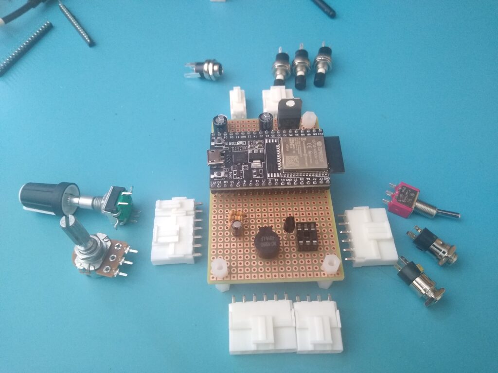
At this point I realized I made a mistake. I bought some connectors assuming they’d fit the protoboard pitch. They don’t. I need to read those datasheets more closely! I’ll make them work.
While all this helped me visualize the final protoboard layout and definitely was sufficient for a protoboard, I wanted something more formal; something that could be used to create a PCB if I ever decide to revisit this project. For that I decided to use Kicad.
Protoboard Layout in Kicad
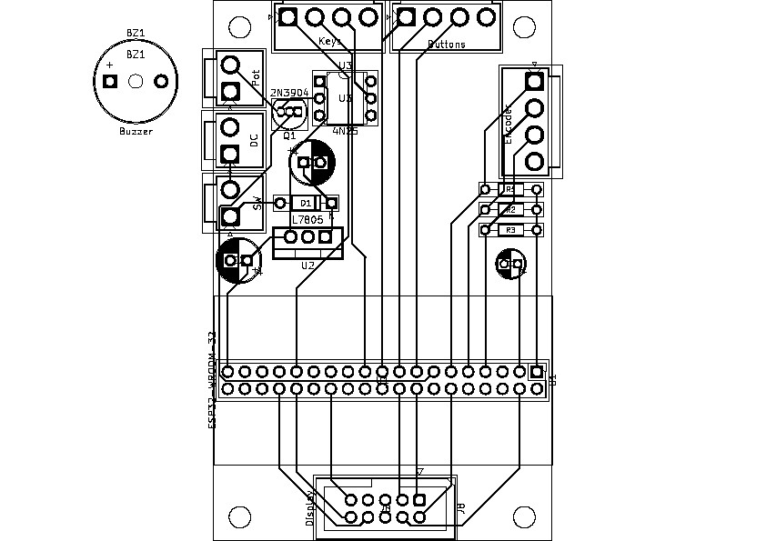
Using Kicad to layout my CW Messenger protoboard is overkill and given that I haven’t used it in a few years, it’s a bit of a hassle. I probably could have had the thing built in the time it took me to create the schematic and PCB layout. But this way I’ll have complete documentation of the build. Here’s an initial schematic, including all of the various connectors I’m using.
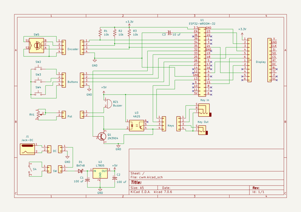
The connectors are overkill for such a small project, but it will help if I decide to do any modifications in the future, especially considering the small case I plan to mount this in.
It took a while to layout the prototype board. This will nicely document all of the wiring (something I think the project author had a problem with based on comments on his website).
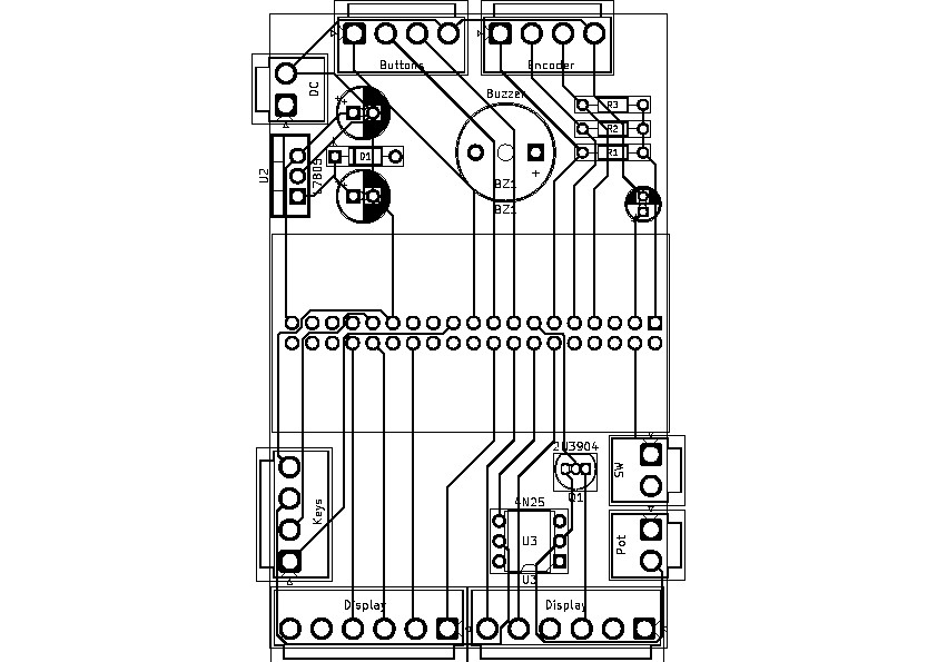
I had to modify the schematic above to make routing traces easier though I’ve maintained the connections to the ESP32-WROOM-32 module as specified in the software (no need to document the schematic again, I’ll change it several more times as I move along). The schematic could be simplified by reassigning these connections to other pins, but I think maintaining consistency with the software reduces problems if others use this. I left some connections to be hardwired for now, though I might revisit this if I ever produce this as a PCB. I didn’t create a footprint for the ESP32-WROOM-32 module though, as at this point that seemed like overkill.
It’s time to prepare the actual protoboard now that I have a layout.
Less than successful attempt at my first protoboard
I haven’t made much progress on my CW Messenger project.
First, my order of IDC ribbon cable connectors came in so I updated the schematic and protoboard layout to accommodate that. I also moved the rest of the connectors to the other end of the board, more in line with their protoboard wiring rather than the placement of their associated component within the case. This would make it easier to create my own PCB at some point. Not really necessary, but another learning experience I want to try out.
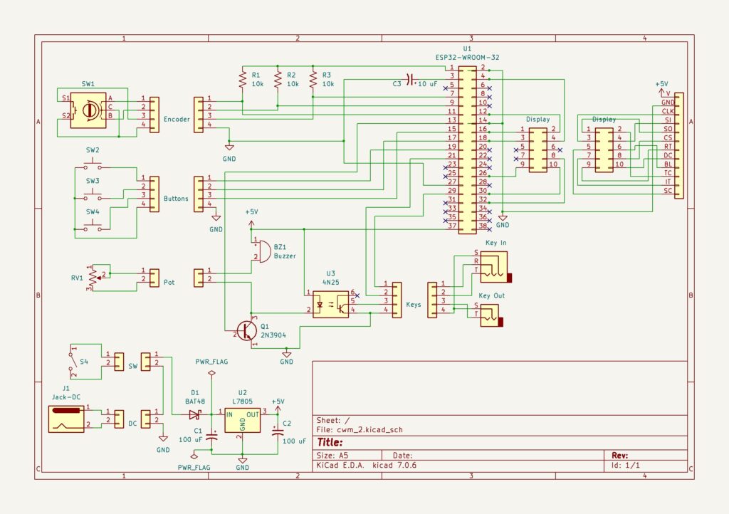
With that completed I could finally begin building this thing.
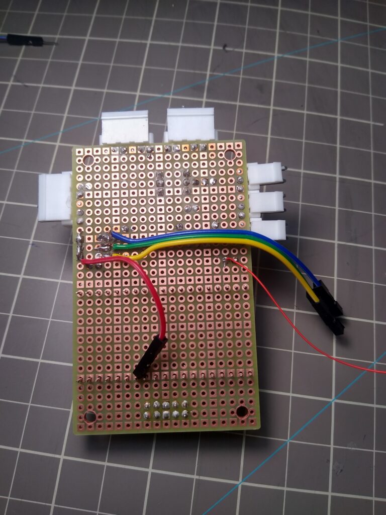
I mentioned previously that the VH connectors that I purchased were the wrong pitch, but given that my local component supplier doesn’t carry the proper ones, I decided to make do with these, mounting them on their side at the edge of the protoboard. The pin pitch was such that every other connector pin aligned with every fourth hole on the protoboard and the pin in between fell between the two intervening holes. I’d solder a wire around every other connector pin through these holes to add some extra support.
I added the first two connectors in this way at the top of the board without much difficulty, though tacking the connectors to the board required more time/heat than if they were mounted as intended. As such I had a bit of work to do realigning some pins. I then moved on to the connectors on the right side of the board. This lead to my first problem. I forgot I was working on the back of the protoboard and mounted the right-hand side connectors to the left-hand side of the board!
I had thought some about the construction of the protoboard and had intended to mount the VH connectors with the pins tacked to the back of the board, thus hiding what were bound to be unsightly connections. The connectors at the top of the board were symmetrically placed so during the time spent in mounting them, I forgot that I was actually working on the back side of the board. I was so relieved at successfully attaching the first set of connectors that I jump directly into attaching the next ones, forgetting that I had to mirror them from their position in the prototype, which was front-side up. I didn’t realize my error until I completed adding the connectors to the left-hand side of the board as well.
Now this really isn’t much of a problem for a protoboard, just a boneheaded move. That’s an advantage of a hand-wired protoboard. I could use the board as planned with some longer wiring. I decided to use the board as is though, with the connector pins tacked to the upper side of the protoboard. This has one issue compared to my original plan. It would be a bit more difficult detaching the VH connectors as the latch would now be on the underside of the board
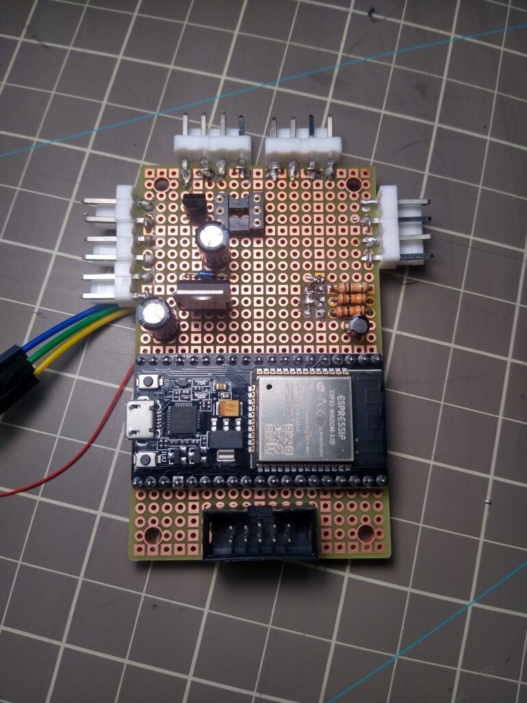
Installing most of the other components to the protoboard was straightforward, except for the socket for the ESP32-WROOM-32 development board, the heart of the CW Messenger. I hadn’t previously tested the socket, but figured I better, before soldering it in. Good thing I did. I had planned to use a machined socket that I have on hand to mount the development board. Trying this out on my prototype I realized that the development board header pins were too big for the socket. I needed female pin headers, but didn’t have a sufficient quantity for this board.
Not wanting to further delay this build or permanently solder the development board, I decided to use jumper wires with a female pin head. There was just enough of the development board header pins on the underside of the protoboard to accommodate this.
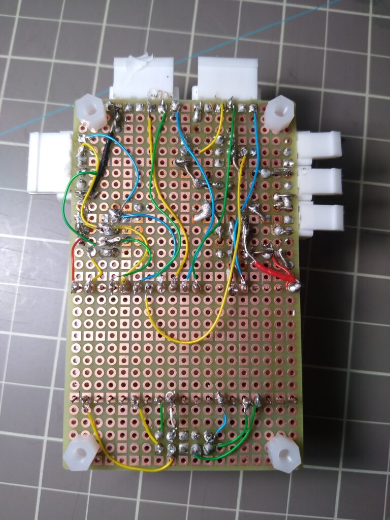
I got to work preparing the jumper wires but this proved difficult because the wire in my jumpers is such poor quality. It was very difficult to tin them and as a result very difficult to tack them to the connections on the underside of the protoboard. I spent about an hour, maybe more, trying different ways to connect just four wires before giving up. Just as a test, I had no problem tacking a pre-tinned 30-guage wire. Here are a few images of my less than spectacular results so far. The big mess of solder by the resistors on the middle-right of the board is the result of my various attempts at attaching their associated jumper wires.
Where do I go from here? I’ve spent so much time on this project already that I really just want to get it done. I’ll probably just move ahead using my pre-tinned wire, hopefully without any more hiccups. This may prevent me from reusing the ESP32 development board, but maybe some neat wiring will allow even that.
Trying Another Approach
I’m making a bit of progress on the CW Messenger build. I’ve got most of the power and ground connections wired on the board. Here’s a photo showing the L7805 output of 5 volts, converting from a 12 volt DC input.
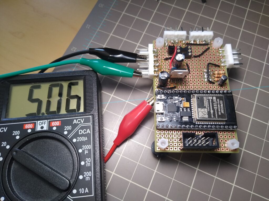
I routed several of the power/ground connections on the top of the board. This helped make the connections easier on the underside of the board.
Tomorrow I’ll wire up the various signal connections to the ESP32. I’ll make those with 30 gauge wire so it should go faster. I had to pick up a new wire stripper for it. The Radio Shack wire stripper I’ve used since high school only went to 22 gauge. It has served me well for a very long time.
Lessons Learned
I’ve learned several thing with this build so far. First, I don’t really care for protoboard construction. While I don’t like to put my projects on hold waiting for prototype PCBs to be produced, after this experience, I think that I would rather the wait than the hassle I’ve had so far (of course much of that is due to this being my first protoboard).
Second, I’m really struggling with lead-free solder. I’ve already gone through a soldering tip with the few projects I’ve done so far and my second tip isn’t in the best of shape either. Getting more practice will help here as well, but I’ve got some 40% lead solder on the way to test. I avoided this when my girls were young, but those days are long past.
Third, I would have had an easier time if I had made the power connections at the same time I was soldering the through-hole components. The component leads could have been used to make the connections between several components and would have served as convenient connection points for others. Doing that would have avoided all of my work this morning. On the flip side, having all of those through-hole leads stinking out the back of the board would have made connecting and soldering the wire connections harder.
Fourth, my eyes aren’t what the used to be. I struggled a bit. Not like the old days. My magnifying glass wasn’t very useful as it tended to block the light, though I noticed enlarging a cellphone photo of the build was helpful. I’ve got one of those lighted magnifier third-hand setups on the way. It’s got to be better than what I’m doing now.
(Looking back as I review this, I think much of this is still true, but less so given my newly gained experience and tools. With some soldering practice, I seem to be able to keep my soldering tip better tinned. Still I don’t remember having this problem in the old days. Are tips today of less quality than before? Is this a price thing? If so, I’d just rather pay more for a soldering tip that lasts a long time.)
Completing the Wiring
The on-board wiring is complete for my CW Messenger project. (A comparison with the schematic or PCB layout will show that this is not true.)
It’s not a work of art and I’m not proud of it, but hopefully it works. I’ll wire up a few of the external components and do some testing tomorrow.
Connecting the external components
I got the power/switch, display and one push button connected. I couldn’t wait to test it out.
I decided to power the display directly from the 5 volt source instead of the 3.3 volt feed from the ESP32 development board. The display and program work normally. The button isn’t working though. I have some troubleshooting to do.
Looking back at some of my earlier photos, I see that I have the wiring to the button connector off by one, so the button in the photo above is not connected to the ESP32 development board. I’ll correct that tomorrow.
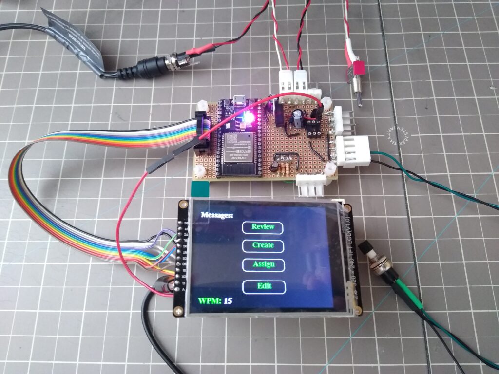
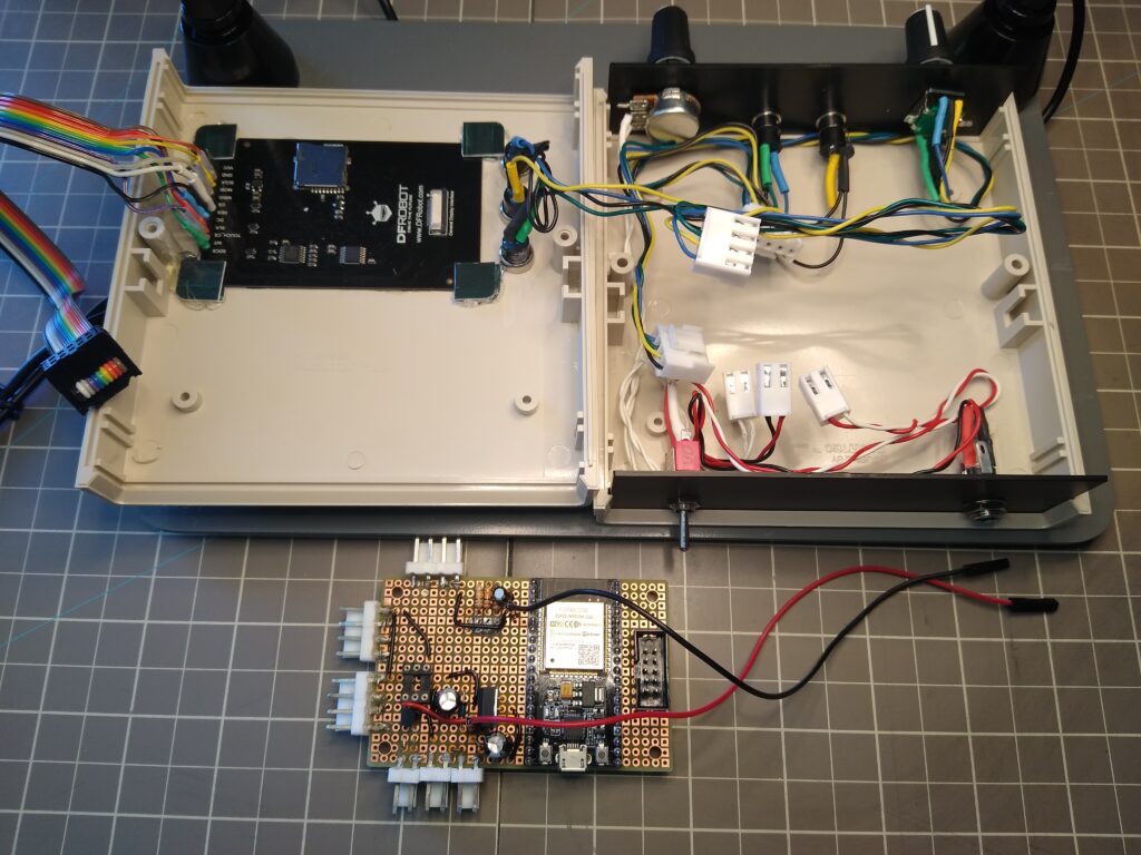
Here’s the build after attaching a few more components.
Only the encoder, potentiometer and buzzer left to wire. All three buttons work now.
I left the encoder and potentiometer until tomorrow. My third-hand kit arrives today which should make wiring them easier. In hindsight, I should have ordered them with different connections (I picked a breadboardable encoder for my initial testing).
The display has 10 signals, just matching the ribbon cable I’m using, so I ran power to it directly from the main board. Initially, I planned to run this through the ribbon cable as this project only uses seven of the display signals. However, I decided to connect all of the signals to the ribbon cable to allow easily adding future capabilities. That left me having to run power to the display separately.
I’ve been thinking about what case to use with this project. I’d like to build a small handheld unit with the display mounted on the top and with the send buttons along the side of the display. I decided to get an inexpensive CNC router to handle creating the openings in the case I bought. That purchase will also let me try out creating my own PCBs. My first test of that will be one for this project. Overkill, but the parts for the CW Messenger project aren’t very expensive so it makes for a good test project for PCB milling.
Quick Test
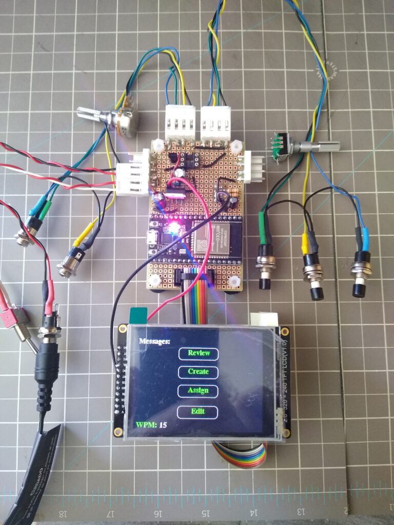
I completed the wiring for my CW Messenger project (except for the buzzer which I haven’t replaced yet). Here is a quick testing video using the S-Pixie buzzer temporarily attached.
The potentiometer isn’t a good match for this buzzer. I’ll need to reevaluate it when I get the actual buzzer I’ll be using. The third-hand kit I got yesterday really helped with the final wiring. I wish I had it earlier in the build.
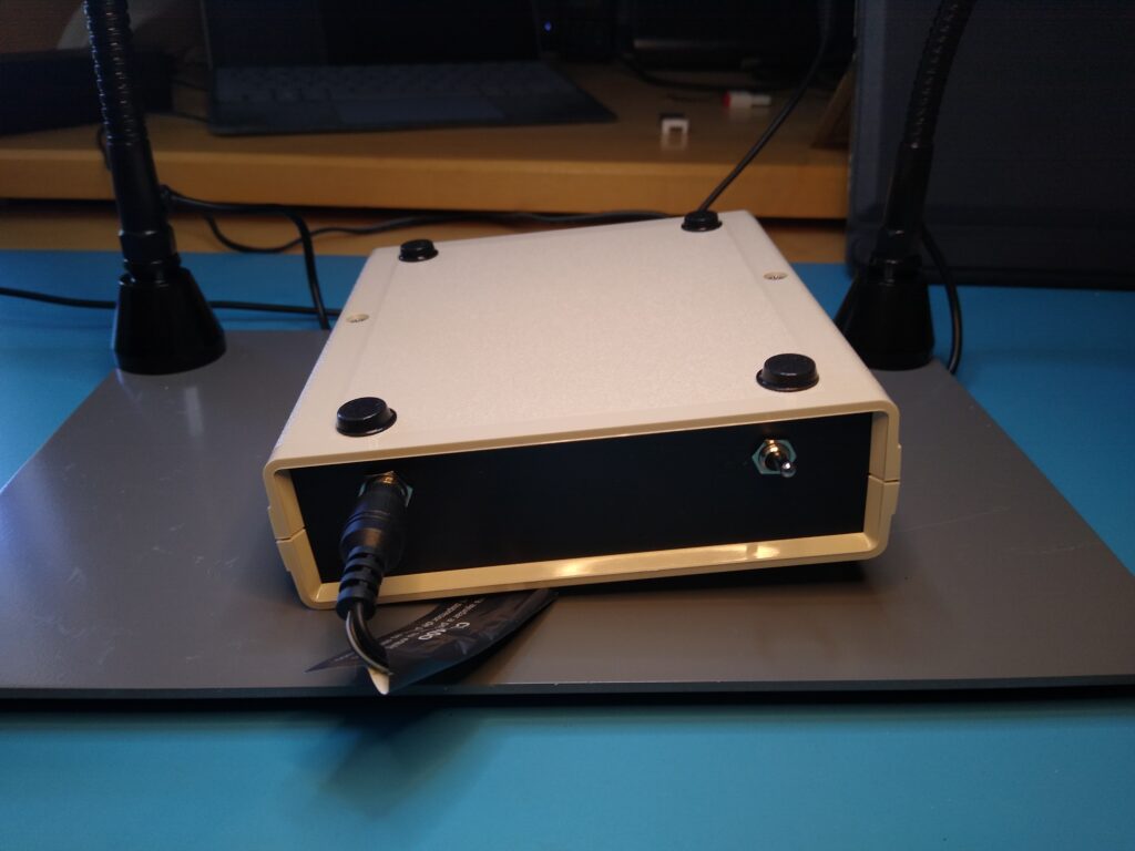
The Final Build
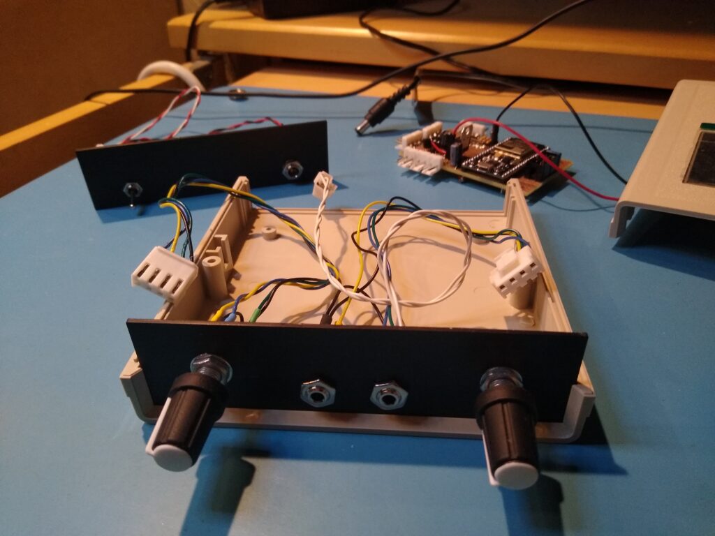
I’m ready to start laying the project out in a case. Here is the rough layout I’m considering.
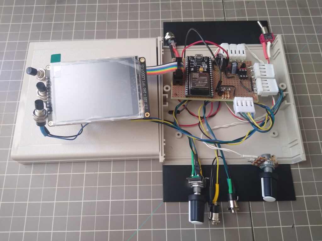
The wiring is a bit messy. I left it long to give me some flexibility in case I decide to change the layout. I can shorten it up once I finalize the layout.
Now I need to do some testing on cutting openings in plastic panels.
CNC Milling: Assembly
I got a Genmitsu 3018-PROVer V2 and a few accessories for sale from Amazon on prime day. There are some less expensive machines out there and of course much more expensive one. This one, at least at the prime day sale price, seemed about right for my hobby work. You can probably get something just as good directly from China for less. You might wait awhile for it to be delivered though (note that Amazon prime day purchases aren’t delivered in two days; it took more than a week for mine to arrive).
The CNC mill was very well packaged for shipment and arrived, in a box clearly displaying its contents, without incident. Interestingly the post office delivered it. Does Amazon offload delivery of heavier packages to them?
Assembly of the CNC mill was straightforward. The included instructions were clear and easy to follow. I did have one hiccup though, and on the first step at that. One of the bolts used to fix the milling bed to the machine was not formed properly. It took Sain Smart a day or so to get back to me regarding a replacement and after a bit of back and forth they agreed to send me a replacement. I haven’t received the replacement yet (or even a shipping notice, though I did get an order confirmation). I’ll hope for the best. Update: I receive the replacement bolt on 8/3/2023. Considering it came all the way from China, that’s impressive. Still, I think their US distributor should have spares on hand, available for immediate delivery. I wonder how many people would just have returned the entire unit to Amazon for replacement.
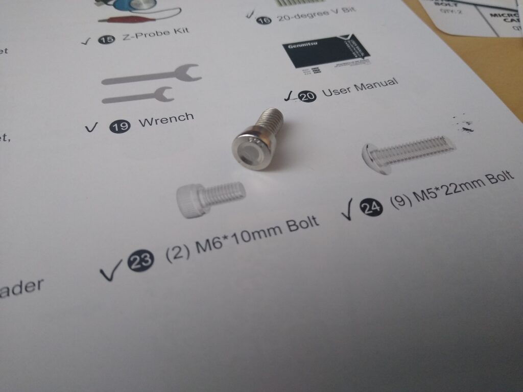
In the meantime, I used an extra bolt that came with the MDF Spoil Board. It’s not the same bolt and likely won’t hold as securely, but at least it seems adequate to allow me to do some testing and initial milling. It’s interesting that with all of the other bolts included with the CNC mill and the spoilboard as well, one extra bolt was provided, except for the M6 bolt that was bad. I’m guessing that this is a hard defect to catch, but it does cause a bit of annoyance, especially right at the beginning of the assembly process. Luckily everything went smoothly after that and I was ready to test the machine. That wouldn’t have been the case if I didn’t have the spoilboard kit on hand.
Here is the mill in the CNC Enclosure I also bought on prime day. I got this to cut down on the noise and dust, but so far I haven’t found either to be as much of a problem as I’ve read about.
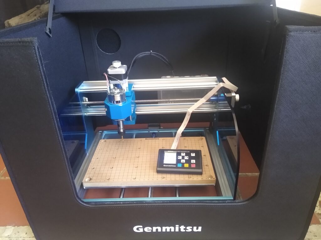
The spoil board is a bit overkill. It’s so nice that I don’t even want to use it as such. And if it’s not going to be used as a spoil board it’s just taking up headroom that could be used for a project. Still the alignment markings have been useful so far.
CNC Milling: Testing
The rest of the user manual wasn’t very helpful in getting up and running with the mill, but Sain Smart provide a resource page for the machine that is much more helpful. With that it wasn’t very difficult to try out one or two of their test G-Code files on a scrape piece of wood. I would have liked a more user friendly experience here though, especially considering that the buyer doesn’t have any experience with these machines.
It was a bit harder to try out the machine on a simple project though. The resource page list several programs and web apps that will generate the necessary G-Code file from your design but most (all?) aren’t priced for the hobbyist in mind, at least for the casual user. Several of the offerings have free trials.
I was attracted initially to Easel, as it’s featured in an article announcing a partnership between Sain Smart and it’s creator, Inventables. I figured this meant that Easel would be geared for the machines and milling bits offered by Sain Smart. This was particularly interesting to me since I had bought some extra bits with my purchase.
Easel was easy to set up and begin using. Perhaps it was just my inexperience, but I didn’t notice much customization with regard to Sain Smart in the Easel web app. I couldn’t find any way to select or import bits sold by Sain Smart. Some of the other software packages seemed to offer this capability.
The 30-day free trial highlights the features available in the Pro version of the app. It seems that many options a hobbyist would want to use are Pro features. To me these features seemed like they should be basic offerings. Even so, I can’t see paying the several hundred dollar annual fee for occasional use. I wouldn’t even pay that as a one-time fee. To me, a onetime fee of $50 was about right for the features offered. YMMV. It seems like subscriptions are all the rage now though. I’ll have to keep looking for a less expensive option.
I mocked up the top of my CW Messenger case in Easel and ran a few test cuts on a piece of basswood. These came out well and my components fit so I moved on to cutting the actual case top. I would have rather ran a test on a plastic sample but I didn’t have any. I did have spare tops for the case, so if this didn’t work out I could try again and I would then have some scrap plastic to play around with.
Milling the CW Messenger Case Top
With what seemed like a crash course in CNC milling, I cut out the openings for the top of my CW Messenger. From my testing and reading, I knew that specifying the bit being used for the cut was important. Sain Smart provides various guides and data regarding their bit. This is all a bit overwhelming for a beginner. Having it integrated or able to be integrated into the Easel app would have been nice. Maybe that’s only possible in the much more expensive packages.
Sain Smart provides router bit databases for various programs (not Easel) and a generic table of bit information for other uses. The various databases seem to contain the same information, just in different formats. Based on the disclaimer at the top of the file, these all seem to be derived from a user’s work, though the source isn’t specified.
There wasn’t any information in the database about cutting ABS plastic, only acrylic, so I went with that. The database suggested ball-nose bits for the cuts I was doing. I couldn’t find a way to specify this type of bit in Easel. I could select a ball-nose bit from the bit pallet but it wouldn’t populate in the tool. This might have been the cause of under-drilling the hole size I was about to experience.
Easel has a dropdown that specifies the cutting parameters for each selected bit. Since I couldn’t import data for my specific bits, these were way off from the recommended values. I read enough about people breaking bits and melting plastic that I wanted to get these right and be conservatives at that. Luckily, Easel allows you to manual enter some characteristics for the bits you’re going to use.
Easel seems to allow (perhaps assume) two bits to be used in a project, one for a rough cut and one for finishing. If only one bit is specified, it serves both of these purposes. I don’t know how it determines which cuts are made as rough cuts and which as finishing, but for my project, the button holes had both rough and finish cuts while the display opening only had a finish cut.
The Sain Smart database only has data for finish cuts for acrylic. I originally selected two bits, a 3.175 mm bit for the rough cut and a 1 mm bit for the finish cut. I manually set the bit parameters to those in the database for finishing acrylic. Easel estimated a few minutes for the rough cut and over 10 hours for finishing. I need to learn more about the purpose of each of these cuts, but that was ridiculous. Likely my bit selection wasn’t consistent with the intended purpose of each cut. In any case, I wasn’t going to run the router for that length of time to make these cuts (and you’re supposed to supervise the machine the whole time!).
I decided to just use the roughing cut. Here are the bit parameters I used (1/8 inch bit: 3.175 mm ball nose):
- Feed rate: 200 mm/min
- Plunge rate: 100 mm/min
- Depth per pass: 0.2 mm
- Spindle speed: 3000 rpm
I forget what Easel’s estimate was for the cut but it actually took about 30 minutes. Here’s a picture of the top after a bit of deburring.
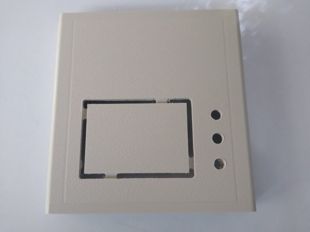
The cuts do not come out as clean as shown, but running a razorblade across the cuts (inside and out) took care of any burrs. I’m pretty happy with the final result, especially considering it was my first project (other than a few test cuts).
I had Easel leave tabs on the scrap piece in the display opening to prevent it causing problems during the cut. This is a nice option that becomes available when you select to cut along the opening outline. I’m not sure if this is a PRO feature or not, but it is handy. I’ll cut off the tabs to free the scrap in the display opening. I’ll use my Dremel. The tabs are recessed toward the inside a couple of millimeters so it shouldn’t be too exacting. This is another Easel option,
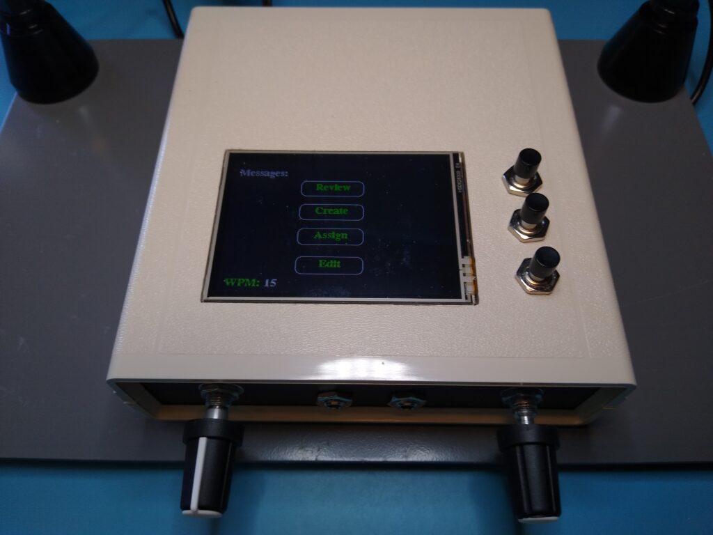
The Completed CW Messenger Case Top
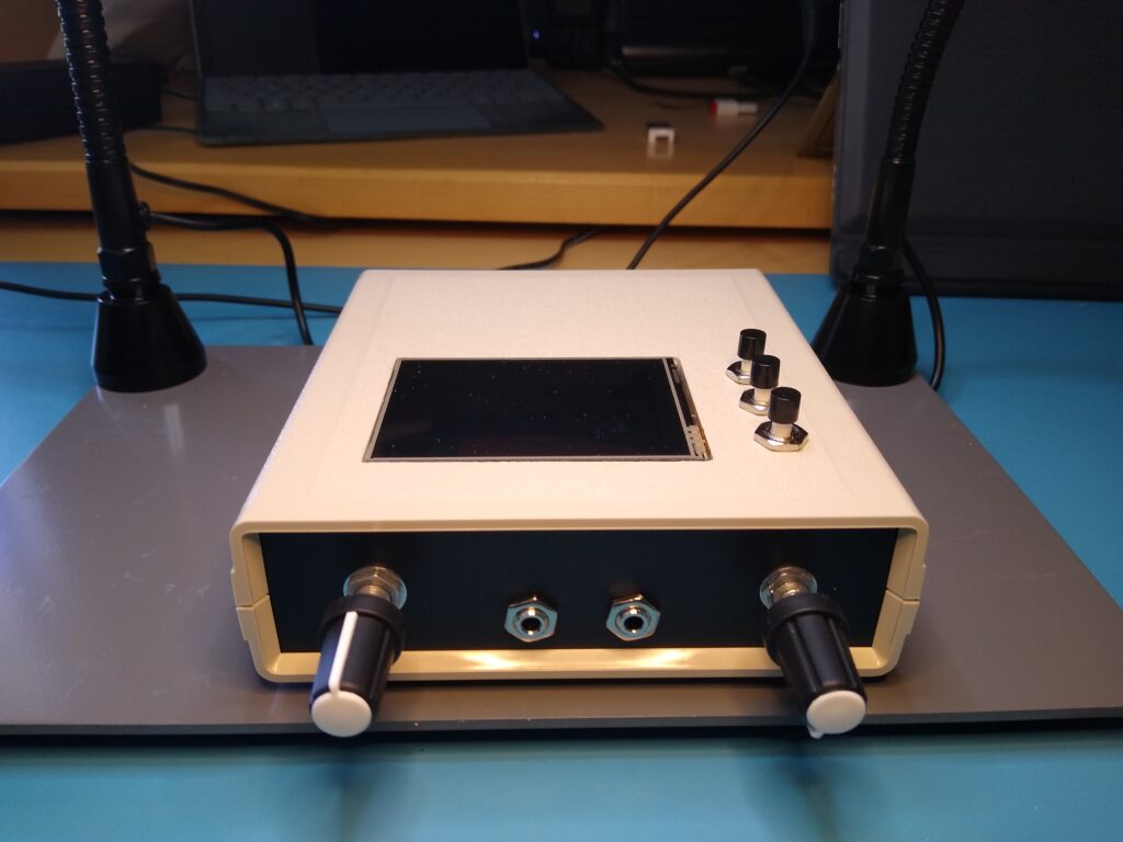
I’ve completed the top of the CW Messenger case, at least functionally.
Removing the scrap piece in the display opening was easy with a Dremel. A low speed works best. Higher speeds melt the plastic (even with just a buffing pad, luckily I didn’t try that on the front of the cover). I also ground down a few mounting posts that were in the way of the display circuit board and the buttons.
The display and buttons fit, but just barely. For a better fit, I squared up the display opening corners with some sandpaper and widened the button holes slightly with a file.
I cut the display opening based on the size of the display’s glass panel figuring that was the viewable area. I see that a portion of the right-hand side of the display is outside the viewable area. It’s a bit unsightly. I’ll probably fix this by adding a bezel.
I still need to decide how to attach the display to the case top (it’s taped in right now). The display circuit board has mounting holes, but I don’t think I want to use them. Maybe I’ll just hot glue it in.
I plan to rewrite the software so that the message associated with each button is displayed next to it. Also, I’d like to allow the unit to be used with the display on the bottom, as shown, or at the top. This allows the buttons to be either on the right-hand or left-hand side of the unit. That will come later though, when I’m back into a programming mood.
I’m getting close to completing the build phase of this project! Now onto the front and back panels.
CW Messenger Case Panels
Front and rear panels assembled.
Interestingly, none of the holes came out the correct size. I think the bit I used wasn’t appropriate for such a shallow hole, at least given the software I used to create the G-Code file. A round file made quick work of enlarging the holes. I’m thinking of engraving labels on the panels. I’ll need to do some testing first to get it right.
Now it’s time to put this thing together.
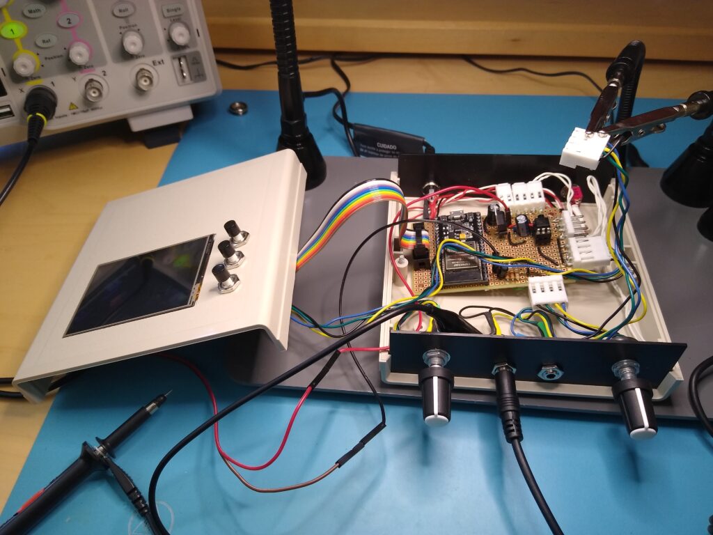
Putting it All Together
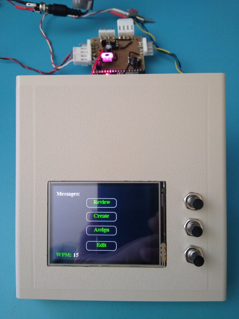
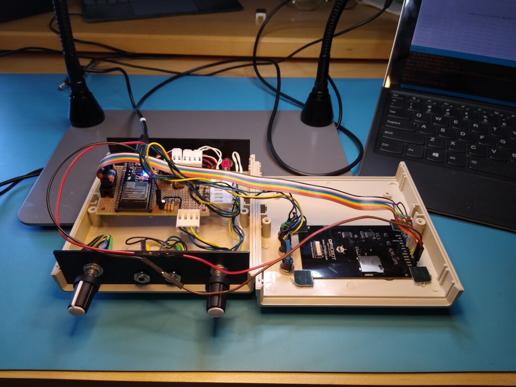
Ready for final ESP32 development board programming and installation.
I attached the display by hot gluing some plastic “corners” at the edges of the circuit board. It worked well and is easily removable if needed. All of the wiring routes well to their board connectors and the excess tucks nicely out of the way. The display ribbon cable and button wiring allow for testing with the top cover open.
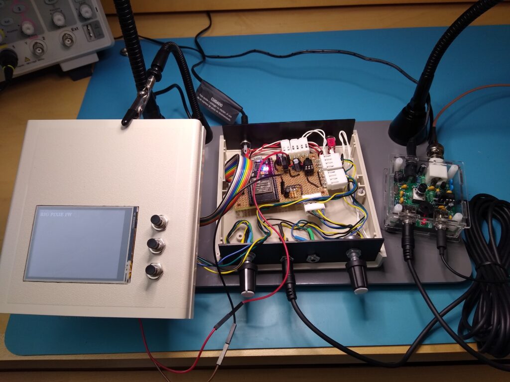
Final Assembly and Testing
I’ve completed phase 1 of my CW Messenger project.
I’m pretty happy with the project so far but I’ve got some more plans for it.
While the final programming went without a hitch. Not so with final testing. Perhaps I was a little overconfident, so I was surprised that nothing happened when I hooked it up to my S-Pixie and pressed button 1 which is programmed to send CQ.
Eagle-eyed readers may have noticed the problem from my previous photos. I had neglected to install the 4N25 optocoupler. I don’t know if it’s a particularly sensitive IC, but I left it out until the end of the build to prevent causing any harm during construction. You might guess as well, that means I hadn’t tested this portion of the circuit on the protoboard build. It worked just fine on the breadboard prototype. That’s overconfidence for you and I was still suffering from it.
I opened the case, installed the optocoupler and a little less confident, decided to this time test the unit before closing it back up. Still no luck. At first I thought I must have wired the key jacks incorrectly. Probing the jacks, I got a signal from the paddle key jack when I pressed a button. That must be the problem. All I had to do was swap the jack tip wires in the connector.
But that didn’t work. In fact I found the same signal on all of the jack wires when a button was pressed. Obviously something more fundamental than swapped wires was involved.
With a bit more troubleshooting I realized that I hadn’t connected pin 2 of the optocoupler. That’s critical as it’s the cathode of the optocoupler’s LED. Nothing was driving the keying circuit without it connected.
A bit humbled, I was back in action after a little board rework and testing (and swapping the key jack wires back).
I’ll revisit this project later to update the message display and add Morse code tutoring features. But now it’s on to testing the S-Pixie transmitter with this unit as its CW keyer. After all, that was the reason for building the CW Messenger.