With my CW Messenger project complete, I can loop back to my S-Pixie project again and begin testing its transmitter. I’ll use the CW Messenger to help with testing until I become proficient in CW.
I’ll start with some simple calling CQ tests of the PCB build, mostly because I’m curious to see what this little thing can do. I’m not expecting much but having spent so much time on the side aspects of this hobby, I’d like to get more time on the air. First, I need to get an antenna up. I played around with one when trying out a crystal radio, put I didn’t put that up properly.
EFHW Antenna
I put up my EFHW antenna (HF Kits end-fed half-wave antenna kit from ARRL) yesterday morning to test the transmitter on the PCB build of my S-Pixie. The antenna is designed for the 10, 15, 20 and 40 meter bands, but I just focused on the 40 meter band for testing the S-Pixie. I’ll look into the other bands when I build my (tr)uSDX, another QRP transceiver that works on the 20, 30, 40, 60, and 80 meter bands. I got it months ago and it’s been sitting waiting to get built. I guess I’ve got a reason to build it now that I have an antenna up.
My property doesn’t have a lot of options for HF antennas. It slopes upward toward the rear and is screened on the sides and back with low trees, none more than probably 25 feet high. I figured the best I could do for my EFHW without erecting a mast would be to connect the lower end to the eave of my roof above where the feedline would enter the house and run the antenna up into the trees at the rear of the property. Given the upward sloping property, I was never going to get great height.
With this configuration in mind, I looked around for a way to string the antenna up into the trees. I’ve read about many methods that I wasn’t sure were going to be very successful for my situation. I needed something heavy but streamlined to get through the bush-like branches of these screening trees. I looked for something similar to a weighted tennis ball, a common choice it seems. The actual thing wasn’t likely to work I thought, being not heavy enough and more likely to get caught up in my trees. Besides, I didn’t have a tennis ball nor anything similar, all such things having been donated once my girls went off to college.
Then I saw a bit of pink peeking out of a pocket in my tool bag. Ah, my plumb line. That might just be the ticket. I’ve never heard of that being used to string up an antenna, but giving it a heft, it seemed to be ideal, heavy, streamlined and with a cord already attached. And I didn’t fret using it for this purpose. I haven’t touched it in over 20 years.
I removed the pointy tip and attached a roll of nylon masons line to the plumb line. I’d have to be careful that the masons line didn’t get tangled in the ivy that covers the area I’d be working in. I found that getting the line tangled with even a single ivy leaf was sufficient to ruin even a powerful throw. Removing the pointy tip seemed a smart thing to do, even if it only meant I didn’t stab myself with it if I feel down.
I was working on a slope after all. I was aiming to get the plumb line up over the screening trees into my backyard beyond. With some care to feed out sufficient mason line and arrange it for the throw without getting caught in the ivy, I gave the plumb a somewhat halfhearted throw. Not having done this before, I wasn’t sure what to expect. I had expectations of it going down the slope and crashing through one of my windows. but it was more like the stereotypical first pitch by an aging politician, halfway there and way off to the side. In my defense, I was in an awkward throwing position, uncertain footing, on sloping ground and with a fence limiting my throwing backswing.
The line missed the taller trees, but still the plumb traveled easily and noiselessly through some shorter trees off to the side and ended up in my yard. The high point of the line was about 15 feet but the far end was only about 8 feet. I knew this wasn’t ideal, but it did make it easier to adjust the antenna length. I decided to go with it, just to see how it performed. I attached the feed point side of my antenna wire to free end of the mason line and pulled the wire through the trees with the plumb line. It went through without hitch.
Completing the installation was straightforward. The antenna kit was pretty complete, lacking only a counterpoise and feedline, which I suppose most kits don’t include. Unfortunately, I don’t have either, or at least what would be most appropriate for my setup. I used the a coax line I think I got with my SDR and some SMA adapters to connect it to the 49:1 balun. I didn’t bother with a counterpoise at this point.
Testing the EFHW Antenna
First up I decided to try to trim the antenna for the 40 meter band. I connected my NanoVNA and measured the SWR for the band. I had previously tested the NanoVNA on some of my mobile antennas, and had saved a test for the band. The SWR was about 1.8 at the lower end of the band and off the chart above 2 at the upper end of the band. The S-Pixie spec is an SWR less than 2, so I could live with this, but I decided to see if I could do better while I had the NanoVNA attached.
I decided to try a counterpoise. I’ve read various reports on the effectiveness of a counterpoise without coming to a conclusion. I looked around my basement and found some old thermostat wire, attaching about 30 feet of it to the balun. I left is resting on top of the ivy. The SWR for the 40 meter band dropped to about 1.5 at the low end to 1.9 at the high end. So, for my setup at least, a counterpoise is useful.
I then turned to trimming the antenna for the band. Since this is a multi-band antenna, the “trimming” amounted to just shortening the antenna by looping it back on itself. I didn’t want to physically shorten the antenna before I test the result on all of the other bands. I’m not sure how this compares to physically shortening the antenna. I’ll need to do some more research. For now I shortened the antenna about a foot and tested the SWR again. It measured a bit better than 1.4 at the low end of the band and about 1.8 at the high end.
Given that the SWR didn’t change much I decided to leave the antenna as is and get on with my testing of the S-Pixie. Since the antenna was completely assembled, I left testing the impedance of the antenna to another day. I wanted to test the S-Pixie out on the air!
Testing the Antenna with SDR
Before I connected the S-Pixie, I tested the antenna with my SDR. As I recall I wasn’t able to receive anything on HF in my earlier “tests” of the antenna. This wasn’t surprising as the antenna was only a couple of feet off the ground. With a more properly configured antenna, I did much better. I heard folks from tens to hundreds of miles away. It’s not clear what power these stations were using but I heard mention levels from 60 to 500 watts. It’s satisfying to have an antenna that’s opened the world, or at lease my small corner of it.
S-Pixie: Testing the Transmitter
I’ve been trying to learn Morse code since I started the CW Messenger project, not too easy for my old ears and slowing mind. I got some encouragement after reading this old post over on r/amateurradio on Reddit where many older hams related that it’s never to late to learn. Still, I’ve been struggling to progress with various apps. So the CW Messenger came in handy, automating my CQ call. I discuss my experience with the CW Messenger later in this post.
I wasn’t too worried about responding to a contact. I had programmed the CW Messenger with likely responses and anyway, the frequency and whole lower portion of the 40 meter band were dead (to me at least). I had listened on my SDR and verified with the S-Pixie when I got everything set up.
I spent the rest of the morning trying to make contacts without any luck. I was also monitoring the Reverse Beacon Network but didn’t notice any spotters detecting my CQ. I’m not very familiar with the network so I can’t say whether this was due to my setup or poor network coverage in my area at that particular time. I did read that spotters are necessarily active at all times.
Antenna Adjustment
After lunch I decided to try to get the antenna up a bit higher to give it another go. With my experience from the morning I was better prepared for the three attempts it took to get the antenna where I wanted it. I prepared a cardboard tube to wind the mason line around. This sped the throwing attempts greatly as in the preparation it kept everything neat and untangled and when throwing, the line smoothly unwound from the tube pointed in the direction of the throw.
Still it took me three throws, each needing just a bit more force to clear the taller tree. After each attempt I detached the plumb from the line and pulled the mason line back through the trees. This seemed easier that the reverse, given that I could wind the line around the cardboard tube as I went. My third attempt wasn’t perfect, but I judged it good enough. And I could just detect a twinge in my arm so I knew a stronger throw had the potential for a strain.
I got the antenna up about another 10 feet or so. I’m guessing it was about 25 feet at its highest, though with the sloping ground and ivy this was hard to judge. I think there was less foliage surrounding the antenna, but this too was difficult to judge from my perspective on the ground. I’ve read that tree foliage doesn’t have much effect on HF bands, but I’ve also read that HF antennas are best place away from trees.
I don’t know if the location of the foliage makes a difference. In the lower configuration, the foliage was closer toward the middle of the antenna. In the higher configuration, the foliage was mostly at the upper end of the antenna.
After securing the antenna in its higher position I retested the SWR. It was back to about 1.5 at the low end of the 40 meter band to 1.9 at the high end. I had expected an improvement with the higher antenna placement, but I also had lengthened the antenna to its full length for the retest. Perhaps that was a more important factor. In any case, it was much harder to adjust the antenna length in its higher configuration, so I left it as is and continued on with testing the S-Pixie. The SWR was well within the S-Pixie’s spec.
Before moving back to the S-Pixie, I retested the higher antenna with my SDR. I hadn’t taken any measurements earlier to compare so I can’t say for certain if the added height helped reception. If anything, I’d say it resulted in a slight improvement, but this could easily be confirmation bias. Unfortunately, I don’t intend to lower the antenna to validate this.
Retesting the S-Pixie Transmitter
The higher antenna proved a bit more successful. While I didn’t make any actual contacts, I did get spotted on the reverse beacon network.
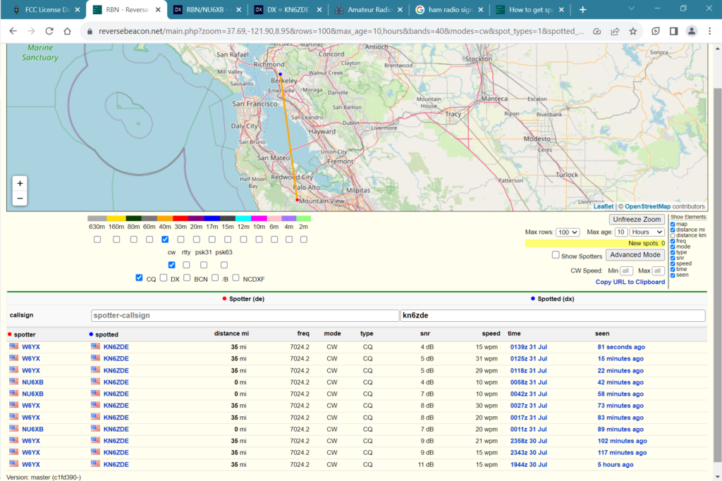
The S-Pixie transmitter is rated at 1.2 W (I need to test it’s actual power output). I got spotted by two local spotters, one within a couple of miles, the other about 35 miles away.
The S-Pixie was spotted on 7.0242 MHz (recall it’s local oscillator frequency is 7.023 MHz). The S-Pixie has a circuit to allow the transmitter frequency to be slightly adjusted. This had no effect on my unit. I’ll need to examine this in the breadboard build.
Toward the end of my afternoon session, I searched the reverse beacon network for my call sign and found that the network had actually spotted me once during my morning session. So the lower antenna wasn’t a total fail. But the higher antenna was spotted 10 times in my afternoon session so the extra height made a difference.
S-Pixie Receiver Selectivity
When receiving with the S-Pixie, I had severe interference from an AM radio station at 910 kHz with the antenna in its higher configuration. The AM station’s transmitter is about 4 miles away and operates at 20,000 watts during the daytime. With the higher antenna, I could clearly hear the radio station and was concerned whether it would mask any responses to my CQ.
I had detected some interference with the lower antenna, but was barely able to make out the signal I was receiving. I couldn’t tell what station it was and wasn’t worried about being able to detect a reply to my CQ.
I’ve read this could be a problem and will need to address it should it prove a problem with other radios going forward. Given the close proximity of the AM station, I’m guessing the problem isn’t isolated to the S-Pixie.
CW Messenger
I successfully used the CW Messenger to get spotted on the reverse beacon network with my S-Pixie.
The unit sends CW correctly at the set speed. I tested CW speed between 10 and 30 wpm. The network usually reported receiving at the set speed but was always within +/- 1 wpm.
My SDR was able to pick up the S-Pixie transmission even without an antenna. Here is a screenshot of the CQ I was using. Unfortunately I didn’t note the CW speed used in this shot.
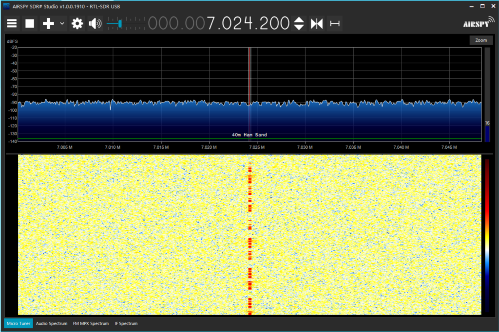
I wonder if I can use this same method to check on harmonic emissions. I’ll have to give it a try. I’ll also be checking on harmonics more formally in comparing the PCB and breadboard builds.
Reverse Beacon Network
With its low transmitter power and its frequency pretty much fixed at 7.023 MHz, I didn’t have much hope of making contacts with the S-Pixie. I figured the Reverse Beacon Network was my best bet and this proved to be the case. I got spotted a total of 11 times in my morning and afternoon sessions combined.
Normally spotters will not respond to the same caller within 10 minutes, so the number of spots within a given period of time is constrained. Still, assuming the two spotters were active the entire time, their reception of my signal wasn’t perfect.
Somewhat telling on the propagation from my antenna, I was spotted more often from a spotter 35 miles to the south compared to one just a couple of miles south. The SNR was also a decibel or two lower with the closer spotter.
The slope of my property should favor a southerly propagation. Is that why I wasn’t getting spotted to the North? Only time will tell. The (tr)uSDX is a 5 W transceiver so that may give some indication.
Given that the SNR of the signal received by the spotters decreased throughout the day, it’s hard to tell if raising the antenna had any effect on my signal strength. The one spot I had with the antenna at the lower height was the strongest, but it also falls pretty much inline with the declining trend I saw the rest of the day.