I got Digilent’s Ultimate Analog Discovery 2 Bundle to help with my journey into radio circuits. AD2 is an “USB oscilloscope, logic analyzer, and multi-function instrument that allows users to measure, visualize, generate, record, and control mixed-signal circuits of all kinds. ” Digilent is having a 15% discount sale making the bundle particularly attractive. The ultimate bundle packages an AD2 with a number of different adapter boards, cables and breadboards to make circuit tinkering easy. AD2, like it’s brother Digital Discovery, uses Digilent’s WaveForms software package to provide a PC-based front end for its functions. I’ve used the software off and on with DD for my retro computer work. It’s helped me solve several difficult to troubleshoot digital circuit problems. I’m hoping it will come in handy with analog circuits as well.
Measuring Current with Analog Discovery 2
After calibrating the included 100 MHz probes, I decided to follow along with Digilent’s demonstration of using AD2 to measure current in a simple resistor circuit. AD2 can’t directly measure current, but you can use its math function calculate it indirectly. I decided to use the included BNC adapter to connect to the circuit I built on the included breadboard kit and connected it all with the included breakout board. Here’s Digilent’s schematic:
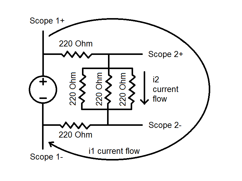
Following along with the demonstration was fairly straightforward (though I think it could have been written more clearly). It also took a bit of time to figure out how to adjust the oscilloscope display. Analyzing the circuit, we can see that current flow i1 should equal i2. That’s not what I was getting though. I was getting about 9.9 mA for i1 and 17.2 mA for i2. Looking deeper I noticed that the scope 2 voltage was 1.24 V. With an input voltage of 5 V, it should have been more like 0.71 V. What was going on?
I measured the voltage across the parallel resistor network with my multimeter. It agreed with theAD2 measurement at 1.24 V so the WaveForms software was showing me a true value. Could there be something wrong with the BNC adapter? It had worked fine as I was calibrating the probes.
I removed the BNC adapter and hooked the AD2 directly to the circuit as shown in the demonstration. Interestingly, I got the correct voltage and current, 0.71 V and 9.8 mA. This was puzzling. Looking at the BNC adapter I could clearly see the positive scope pins routed to the BNC connector. I couldn’t see a trace from the negative scope pins though. Breaking out my multimeter again I found that these pins were connected to ground. Very strange. So, the AD2 scope was able to take differential measurements but the BNC adapter wasn’t. Looking at the BNC adapter reference manual, I found the following note “the negative inputs for both oscilloscope channels are tied to ground, creating single ended inputs with the BNC Adapter board“. This can be seen clearly in the BNC adapter schematic.
A little googling yielded this post in Digilent’s forums warning about this. It seems that this has caused problems for others as well and even for some to create their own adapter boards to allow differential measurements. This adapter looks interesting, but for now I’ll just adjust the setup to measure both voltages across the parallel resistor network with respect to ground and calculate the current using the difference between them.

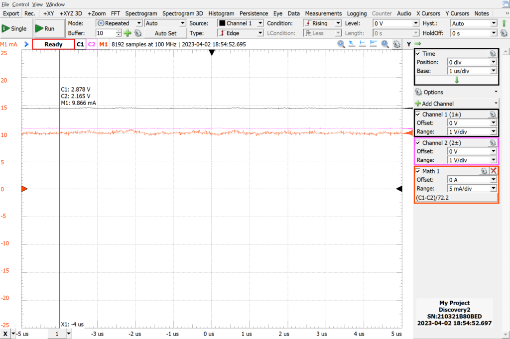
Here you can see the correct calculation of i2 of 9.8 mA.
It’s clear I have a lot more to learn about the AD2, including how to get good images from it.
Let the journey begin!
PS: If you compare the images of the breadboard kit on Digilent’s website and my image above you’ll notice that the breadboards are different. After working with the Digilent breadboard for awhile I decided to swap them out for the type I normally use from BusBoard Prototype Systems. I thought the quality of the Digilent breadboards was fine, but the power rail tie points were too tight, so much so that it was often difficult to insert component leads. Luckily the breadboards are screwed to the base, making replacement easy.
.