I’ve been taking it kind of slow with radio gear purchases since getting licensed. Being more interested in the technical aspects of the hobby, I’ve bought a few small kits to get started with but these have mostly sat waiting me getting the time to assemble them and getting an antenna up. I have built the 1:49 UNUN that came with the HF Kits end-fed half-wave antenna kit I got from ARRL. The antenna works on the 10, 15, 20 and 40 meter bands. Now I just need to figure out where I’m going to put it and how I’m going to get the feedline into the house. Prior to that though I performed a few antenna experiments with just the 66 feet of antenna wire that came with the kit.
Trying out Software Defined Radio
I didn’t have any luck trying to receive HF bands on a software defined radio dongle, RTL-SDR, with the long wire simple strung up either indoors or outdoors, though the dongle worked just fine with its included antennas on the VHF and UHF bands. This isn’t a surprise as they warn in their blog that “direct sampling is not a high performance mode for HF”. For that I’ll have to wait until I can get the antenna properly installed.
I had more luck tuning into broadcast AM stations with the long wire on the SDR dongle, no doubt because of their relatively strong signal strength. There wasn’t much to play with, antenna wise though, almost any random wire was sufficient to pick up these stations. This got me thinking, why not build my own AM receiver? There is plenty of information online about this, here for example. I decided to try to build a crystal radio to experiment with.
Experimenting with a Crystal Radio
I remember building a crystal radio from a kit when I was a boy. I particularly remember having trouble getting a good ground and having to sit by the radiator so I could attach the ground wire to the radiator pipe. I don’t recall much more about using the radio, but I doubt it got many more hours of my attention. It was the start of my interest in electronics though.
I decided to build the crystal radio circuit shown in the link above:
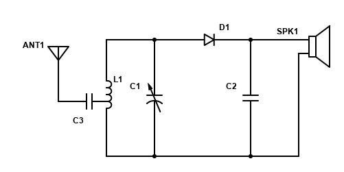
BTW: DigiKey has a nice browser app to create simple schematic diagrams like this.
I’ve built up a fair collection of electronic parts with my 6502 experiments, but I don’t have many parts useful for building radio circuits. I’ll have to remedy that. In the meantime, I decided to scavenge around for a tapped coil and variable capacitor that I would need to tune this radio. The other parts I had available, though I’d have to use a normal diode in place of the recommended germanium diode, which I don’t have. The speaker of course is a high impedance earphone typical of crystal radios. I had picked one up earlier thinking it would make a handy addition to my radio components kit.
Of course, I was hit by the old adage of whenever you throw something away, you’re bound to want it soon after. While I didn’t think I had any suitable tapped coils or variable capacitors lying about, I was certain I at least had an old AM radio that I could scavenge some parts from. I had no luck in my search though. I guess they’ve all been donated or recycled as part of clearing out old stuff during the COVID years. I did find a power transformer with a center tap on the primary winding and a variable capacitor that are parts in a Snap Circuits kit I bought for my girls when they were young. I might be able to work with these though I didn’t want to ruin the kits by salvaging the components for my breadboard project. Then I noticed two surface mounted coil breakout boards in my Analog Devices ADALP2000 Analog Parts kit. I’d never looked into these Hexa-Path transformers before but a quick glance at the datasheet showed that I could create a tapped coil for the project. I figured for antenna testing it would be a simple matter just to use discrete capacitors to manually tune the radio to a strong station for testing.
The HP1 Hexa-Path components in my kit have 6 individual windings around a common ferrite core. The individual windings can be connected in various configurations, including in series to create a tapped inductor that I needed for this project.

The tap between winding L5 and L6 would give about the same relative winding ratio as recommended, but what would the overall inductance be? The datasheet gives a simple formula as the inductance of an individual winding multiplied by the number of windings squared. The winding inductance of the two components I have are 27.4 and 202 micro-Henrys, or an overall inductance of 986 and 7272 micro-Henrys respectively for the inductor configuration shown above. This is well above the recommended value. I’d have to make some adjustments either by excluding a winding from the overall coil, adding another inductor in parallel such as these handy breadboard-able inductors that were also included in the Analog Devices parts kit, or altering the matching capacitor.
Without a good variable capacitor, I figured the best approach would be to create an LC circuit that would resonate at the frequency of one of the stronger stations in my area. Using the formula for the resonant frequency of a LC circuit, f=1/[2πsqrt(LC)], I could create an LC circuit that resonated within the AM band, 540 kHz up to 1700 kHz, using the smaller Hexa-Path transformer configured as above and capacitors between 10 and 100 pF.
I have a number of different capacitors in this range so finding one to tune into a specific station may not be too difficult. A 10 pF capacitor should be resonant at 1602 kHz and a 100 pF capacitor should be resonant at 507 kHz. There are about a dozen strong AM stations in my area. I should be able to find one that is a good match for the capacitors I have.
Of course, this is all theoretical. Let’s measure the actual frequency response of the tank circuit using Digilent’s Analog Discovery 2 network analyzer. I’ve used the Analog Discovery 2 in a few of the lab experiments in Digilent’s Real Analog Circuits course. Hopefully I’ve learned a few more things since I posted about it in April.
Frequency Response of the Tank Circuit
At the end of this post, I’ve included a partial writeup of my original analysis of the frequency response of the tank circuit. In it I struggled with understanding the Network Analyzer results. Below, I’ve reworked this using the Impedance Analyzer. I still want to revisit this portion of the experiment using the Network Analyzer.
The inductor and capacitor values for the AM band frequencies noted above assume an ideal capacitor and inductor. However, this isn’t the case in real-life. Let’s look at how the reactance of the inductor I’m using varies over the AM band frequency range. First, the theoretical reactance of the inductor:

Here is the measured reactance of my inductor using the Analog Discovery 2 Impedance Analyzer Adapter:

You can see that by the start of the AM band, the reactance of the inductor is already well above the theoretical value and approaches infinity somewhat above 800 kHz. At that point the inductor becomes capacitive. This means the inductor will only be able to tune the lower portion of the AM band. It’s possible I could do better by altering the inductor’s configuration or breadboard wiring, but I’ll leave that for another experiment. For reference here is the reactance of one of my breadboard-able inductors, with a similar inductance as the Hexa-Path inductor shown above, 1000 micro-Henry (see the link above for the datasheet).

This inductor could cover most of the AM band, but unfortunately it doesn’t have a tap for the antenna input. Question for the future: Any way around this?
In the graph above I’ve shown the reactance of the inductor at 610 kHz, the frequency of an AM station with a strong signal in my area. When the tank circuit is at resonance, the reactance of the inductor will equal the reactance of the capacitor, so all I need to do is find a capacitor with the same reactance. Theoretically this would be a 35 pF capacitor. I can get close to this by combining a 22 pF and 10 pF capacitor in parallel. Here is the reactance graph of that combination:

And here is the resulting tank circuit reactance with those capacitors and inductor:

You can see that the tank circuit with this capacitor and inductor is resonant at about 610 kHz. As we’ll see later in this post, I was able to tune this station well with just a 22 pF capacitor. I’ll leave for future testing whether the 32 pF capacitor actually results in better reception. And while I played around with various capacitors to tune into another AM station, 740 kHz, I didn’t have enough time to refine it, so here is some data for future testing. An 8 pF capacitor should work best at that frequency.


Experience with the Antenna
As I mentioned, my goal for this project was to experiment with the 66-foot wire that came with my end-feed half-dipole kit. I knew I could tune-in about a dozen strong AM stations on my AM clock radio and I even built the Snap-Circuits AM radio, getting decent reception in my living room where I was conducting some of this experiment. How would the crystal radio perform with this antenna.
As a first test, I just connected the bundled wire to the crystal radio with a 100 pF capacitor, but I didn’t hear anything on the earpiece. I had better results after stringing the wire up in a loop around the perimeter of my living room. I could just barely detect a bit of static on the earpiece, it would have been louder if I had the germanium diode. This prompted me to add an amplifier stage to the crystal radio (discussed below). This isn’t typical of course. A key feature of a crystal radio is that you don’t need power. But without enough volume I wasn’t going to be able to figure out what was going on.
With an amplifier gain of 100, I was able to tell I was hearing the AM station in my area at 740 kHz, but the reception was pretty poor, and I could just barely make out the station call sign.
Now this was before I had done the circuit measurements discussed above, so with a 100 pF capacitor I thought I’d be tuning into a station lower in the AM band. As an experiment, I tried a 10 pF capacitor. I got the same results, I was still hearing the station at 740 kHz, but just barely. In fact, I got the same results with no capacitor at all.
I assume my circuit was simply detecting and amplifying the strongest signal on the antenna. According to the station’s website, it’s signal, which originates not far from my home, reaches quite far around the state at nighttime, when I was performing this portion of the test. They use a different broadcast patten during the day though, so when I tried a similar antenna setup with my SDR the following morning, this station wasn’t as strong as some other stations.
I then decided to try the antenna outdoors. I first tried the antenna out my front door, strung up a couple feet off the ground, draped on some bushes around the front yard. It was in an L configuration. With this I was able to actually tune the circuit and was able to clearly hear the station at 610 kHz with a 22 pF capacitor. In fact, I had enough volume that I had to reduce the gain of the amplifier. I installed a potentiometer to allow me to easily adjust the volume.
With this success, I decided to string the antenna up in my backyard, trying for a better configuration. I was able to get it fairly straight, about 6 feet off the ground. The difference in reception was significant. In fact, I could clearly hear the station at 610 kHz without the amplifier.
With a more “proper” antenna setup, I started playing with tuning the radio, varying both the circuit capacitor and the antenna feed point. I found that without a capacitor, the radio was picking up the station at 910 kHz with the antenna feed point as discussed above. However, if I moved the antenna feed point so more windings were included, the radio picked up the station at 610 kHz. With a 22 pF capacitor installed, the station at 610 kHz was loud and clear, so much so that I didn’t even try to refine it. As discussed above, a 32 pF capacitor should have performed better.
At this point I realized the problem with my setup. Clearly if the circuit was resonating at 610 kHz with a 22 pF capacitor, I wouldn’t be able to tune into much of the AM band. With a 10 pF capacitor I was starting to discern the station at 740 kHz. I didn’t realize at the time my 10 pF capacitors are actually closer to 13 pF and as mentioned above I needed to get to about 8 pF to tune that station well. I was trying various combinations of 10 pF capacitors to get a lower capacitance without much success when I ran out of time for this experiment. For the record, I later worked up the following for a 8 pF capacitor.
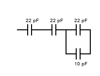
I’ll leave that for future testing if I revisit this experiment.
Audio Amplifier
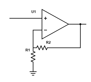
I used a simple non-inverting voltage amplifier to amplify the audio signal in this experiment. Eventually I replaced R1 with a potentiometer to adjust the volume of the crystal radio.
Audio Signal Filtering
I played around with filtering the audio signal a bit at times as well, especially early on when the signal wasn’t coming in very clearly. Capacitor C2 serves as a low pass filter for the signal. I found that increasing the capacitance from the recommended value and adding a resistor at times helped reduce the high frequency noise level.
It was at this point that I started looking into the actual performance of my circuit. Below is the writeup of my original findings. It’s clear now why the results were off when using a 100 pF capacitor, but I’d still like to investigate why the Network and Impedance Analyzer results were so different with a 10 pF capacitor. One factor could be that I was feeding the antenna into the tank circuit through a capacitor as in the crystal radio circuit. I think that affects the Network Analyzer results. I think a more proper setup is given in the first link below.
Addendum: Frequency Response of the Tank Circuit – Original Analysis
Below is my original, incomplete, unedited writeup of my analysis of the frequency response of the tank circuit using the AD2. I’m including it here to remind me of the complications I experienced. I may revisit this in the future.
Hooking up the AD2 to test the frequency response of RC filter circuits is straight forward, they have a clear input and output. But this isn’t so clear for a series or parallel resonant circuits. Luckily Analog Devices has a good tutorial for just this case, Resonance in RLC Circuits. This is part of the Analog Devices Introduction to Electrical Engineering Based Lab Activity Material which is part of their Engineering University Program. There is a lot of great stuff there.
Turns out I could just connect the tank circuit to the AD2 with scope and waveform channels 1 connected to capacitor C3 in place of the antenna and scope channel 2 connected in place of the diode. I got the following frequency response plots.
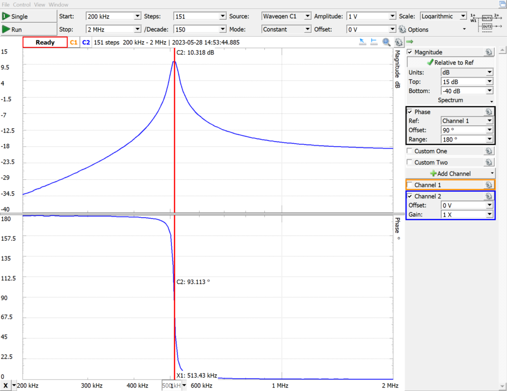
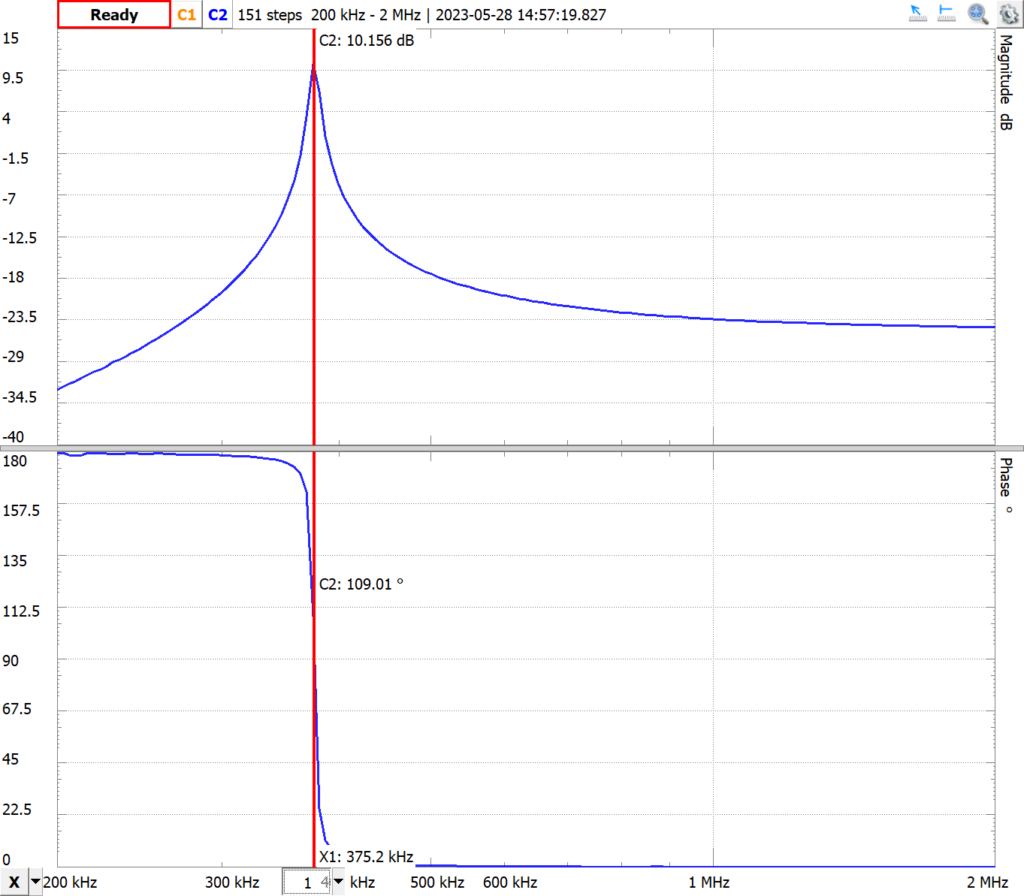
This is quite a bit different from the expected resonance frequencies of 1602 and 507 kHz. There can be several sources for the error. A logical place to look first for a source of error is that the actual values of capacitance and inductance of the tank circuit components are different from their stated values. I’d feel more confident that this was the problem if the results were close as the resonance frequencies above are well beyond what would be expected if the components were at their tolerances. Still, it’s best to verify the component’s values. We can calculate the apparent value of each component using the AD2 to measure each component’s impedance. Digilent specifies some reference circuits to use depending on what component/circuit you’re measuring, but to make this easier, they also sell an Impedance Analyzer Adapter. All of my components are well within tolerance except the 10 pF capacitor which calculates to 13 pF. This doesn’t account for the deviation from the expected values though.
We can also use the Impedance Analyzer to somewhat independently evaluate the resonant frequency of the tank circuit. At resonance, the impedance of the tank circuit will approach infinity. I say somewhat independently because I’m guessing some of the same methodology is used between the Network and Impedance Analyzers.


While these show a resonant frequency somewhat closer to the theoretical values, they are still quite a way off, especially the 10 pF value.
Another possible source of error is parasitic capacitance and inductance in the circuit. I can test for this somewhat by altering my testing setup by shortening connecting wires as much as possible for example. I had mixed luck with this. Shortening the leads to the Impedance Analyzer Adapter did result in a somewhat higher resonant frequency but doing so for the Network Analyzer actually made things worse. Given the sizable change in the wiring for that though, I suppose it’s possible that there was more balanced parasitic capacitance and inductance in the original circuit than my reworked one.
Another possible source of error could be that the AD2 isn’t able to measure as accurately in the range I’m testing. I don’t think this is likely. The AD2 seemed to compare just fine with theoretical on some very simple circuits I tested.
Another possible source of error is user error. I’m still new to using the AD2 so I suppose it’s possible that I’ve overlooked a setting or something or am misinterpreting something. I’ll look more into this, but for now I think it’s time to get on with the experiment.