The WDC65C02 datasheet says that to initialize the microprocessor and start program execution the reset pin must be held low for at least two clock cycles after the power supply reaches operating voltage. In most cases if this is not done your 6502 based computer will not function properly. Ben Eater’s 6502 computer accomplishes this reset with a simple push button connected between the 6502’s reset pin and ground. Once you power up the computer you must momentarily depress this reset button to begin your program. This isn’t much of an inconvenience for a breadboard hobby computer, but it would be a bit clunky in my planned handheld 6502. I needed a way to automatically reset the 6502 on power up.
There are plenty of resources on the web that discuss various reset circuits. Garth Wilson’s 6502 Primer has a page covering several reset circuits. I tried out a 555-timer reset circuit similar to his in my second 6502 build. Check out the rest of the Garth’s primer too. It’s a great resource as well.

Ben Eater explains the basic operation of a similar circuit in his Monostable 555-Timer video. The circuit above provides a power up reset signal of a little over 0.5 seconds. The delay can be lengthened or shortened by changing the values of R1 and C1. Note that I’ve used an extra NAND gate from the 74HC00 used in my address decoder instead of adding an extra inverter chip to my build.

The circuit also provides for resetting the 6502 during operation.

Note that the reset signal is again a little over 0.5 seconds beginning from when the reset button is first pressed. This is a key characteristic of this circuit. The reset signal coincides with the 555 pin 2 signal. Thus, a long pulse on pin 2 can almost totally subsume the reset signal.

Here a 0.8 second reset button press overwhelms the circuit leaving a reset signal delay of only about 20 milliseconds once the reset button is released. This might not be sufficient depending on your use and how much bounce your push button exhibits.
An alternative mentioned by Garth is Maxim’s DS1813. It’s a single component reset device ideal for my handheld 6502 as it eliminates the external resistors and capacitors used by the 555-timer circuit. It’s reset signal is already inverted as well, saving a NAND gate in my address decoder for another use.
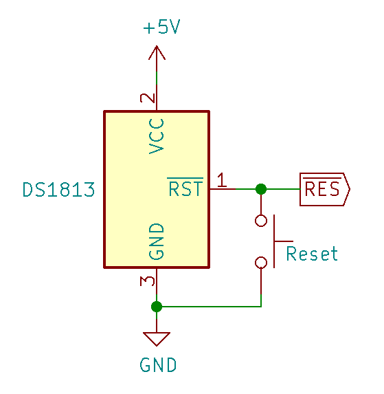
The DS1813 operates different from the 555-timer reset circuit. Unlike the 555-timer reset circuit, the DS1813 maintains a reset signal for about 150 milliseconds after a reset. It also monitors supply voltage and will set the reset signal whenever the voltage is out-of-tolerance, clearing it only after the voltage has returned to tolerance for about 150 milliseconds.
The DS1813 gives a range of between 100 to 300 milliseconds for the reset delay, with 150 milliseconds being typical. My DS1813 holds it’s reset signal for about 260 milliseconds after a voltage transient. Here is a trace showing the DS1813’s reset signal following a startup.

After a supply voltage transient, I get the same reset signal after the supply voltage reaches operating level again. Different versions of the DS1813 allow for different tolerance levels from 4 volts to 4.75 volts

One disadvantage of the DS1813 compared to a 555-timer reset circuit is its fixed reset delay. If you need a reset delay longer than 100 to 300 milliseconds then the DS1813 isn’t going to work for you.
I think the DS1813 is going to work out well in my handheld 6502. How about you? Have you used the DS1813 before? Tell me about your experience with it or other reset circuits in the comments.