I enjoy recreating the component tests that Ben Eater performs in his electronics project videos. Sometimes my test results differ enough from Ben’s that I wonder if the component I’m testing is defective. More often than not the component is fine and I’ve either botched the test circuit or have set up the testing equipment incorrectly. Coming to this conclusion though is sometime a long, sometime painful process. It’s always educational though.
Take for example testing a simple crystal oscillator as I did about 5 months ago. Attach power and ground and you get a square wave on the output pin. Hook up an oscilloscope probe, fiddle with some settings and there, you’ve recreated what Ben has done in his 6502 – part 8 video.
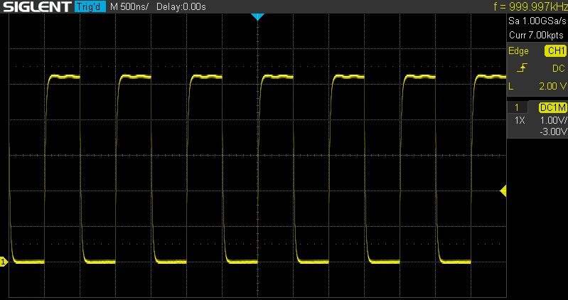
Or have you? My trace doesn’t look quite as crisp on the leading edge as the one in Ben’s video. His equipment probably has a lot better resolution than mine though, so, close enough at this scale, right?
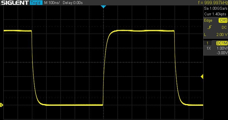
Continuing on, Ben zooms in to look at the crystal oscillator’s rise time in more detail. Maybe that will help with the softness I’m seeing on the leading edge. But at a 100 nanosecond scale things don’t look any better.
Ben’s is showing a nice crisp trace on the leading edge. And zooming in further, as Ben does, clearly shows I have a problem. I can’t even fit my trace on the 5 nanosecond scale as Ben does but have to use a 10 nanosecond scale instead.
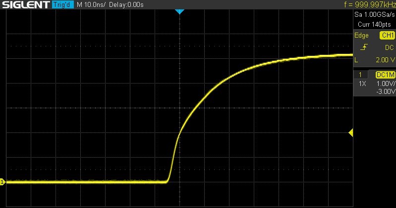
Ben’s crystal oscillator rises from 0 to 5 volts in about 3 nanoseconds. Mine only gets to 4 volts in about 20 nanoseconds and it’s rise to 5 volts continues at an even slower rate. My oscilloscope isn’t as fancy as Ben’s, but it isn’t a super cheap one either. Surely, the quality of my oscilloscope can’t explain that much difference in our traces.
Ok, maybe the crystal oscillator that comes with Ben’s kit is different than the one he’s using in his video, the markings are slightly different after all. Maybe the two crystal oscillators have different specifications that will explain the difference in the traces. Let’s track down the specs for my crystal oscillator.
The crystal oscillator that I have has no identifying marks other than it’s 1 MHz frequency so tracking down it’s specifications will never be a certainty, but maybe these components are standard enough to explain what I’m seeing on my scope. I got Ben’s 6502 kit from Jameco and I found a 1 MHz crystal oscillator on their website. The data sheet only shows the pinout but the webpage lists a Rise and Fall Time of 15 nanoseconds. We’re getting somewhere. This spec is closer to what I’m seeing. But how are these times measured?
A google search leads to a few helpful clues. On one, a crystal oscillator manufacturer said the Rise Time is “the time it takes when the output waveform changes from ‘L’ level to ‘H’ level” and visa-versa for the Fall Time. So, what’s a low and high level? TTL voltages maybe? Digging further I find one of their crystal oscillators specifies this as 20% to 80% of the waveform. Now the crystal oscillator with this spec is much more sophisticated than the one I’m using, but having nothing better, let’s see what rise time I get with this range.
A 20-80% range on my 5 volt waveform is between 1 and 4 volts and from my oscilloscope trace above that gives a rise time of about 18 nanoseconds. That’s not far from the spec listed on the Jameco site, so maybe everything is ok after all. Maybe the kit just includes a crystal oscillator with a longer rise time spec than the one Ben uses in his video. But if so, I wondered, how that will affect the 6502, if at all?
I couldn’t find any information on the web, so I asked the question on Ben Eater’s subreddit. A good discussion followed but nothing definitive regarding whether I had a good crystal oscillator or not, or whether it would affect my project at some point. It did highlight that I needed to understand my oscilloscope better, but that required time I didn’t have, so I moved on to other things and mostly forgot about the issue.
As I alluded to above, these problems are often the result of user error. And that’s the case here as well. I’m not sure when I took the time to learn how to use my oscilloscope properly, probably a bit at a time. There are still features that I haven’t used yet. I found the manual unhelpful. It mostly just lists features and states what buttons to press to enable various options. It contained no explanations for why you’d want to use a particular option over another.
But with trial and error I came to know my oscilloscope better and found that I could get higher resolution traces when I set my probe to the 10X scale. This requires an option change on the oscilloscope to scale things properly. Reading the manual did help with knowing that setting was available!
And here we are, 5 months later. I haven’t considered the rise/fall time of my crystal oscillator much since my reddit post. Recently, as I was testing the use of bypass capacitors to reduce ringing on the clock line some of my traces brought this topic back to my mind. I had planned to post about bypass capacitors, but it turns out this is a more interesting topic. So, the conclusion?
Recreating Ben Eater’s crystal oscillator Rise Time trace with an oscilloscope probe set to a 10X scale yields a trace just like Ben’s, maybe even a little bit better.
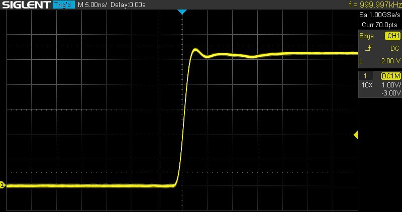
Looking a bit closer at Ben’s oscilloscope screen you can see a 10.0:1 at the bottom. I assume that indicates he’s using a 10X probe setting as well.
I’ve long since learned that when problems arise with these electronics projects that I need to take a deeper look at what I’ve done and how I’m testing. Rarely has the problem been with the components, but rather with my wiring, program or test setup. And if a bad component was the problem, it’s always been something I’ve caused.
So, yes. My crystal oscillator was working correctly and yours probably is as well. Hang in there. It may take months to finally figure things out, but it’s a satisfying feeling when it happens.
Have you had a similar situation, wondering if a component is bad, only to find out later that you weren’t testing it correctly? Tell me about it in the comment section.