I worked on the Build 4 modifications over several weeks, partly because I was just playing around with what I had on hand when I started and partly getting sidetracked looking into why things happen instead of just getting on with the build. In this post I discuss troubleshooting the memory corruption issues I found. In another post, I discuss modifying Build 4 in more detail and in another post, I discuss my investigations regarding the PLD that’s featured in this build.
My barebones version of my 6502 Build 4 ran just fine with a 65816, at least as far as I could test it. Without keyboard support I could only base my assessment on seeing the proper startup splash screen and the initialization of my Forth operating system. With that success, I decided to continue modifying Build 4 for the 65816. See more about modifying Build 4 for the 65816 here.
What followed was weeks of investigation, a new oscilloscope and a much better understanding of how these processors behave in the real world. This post is a story of part of that journey.
Adding the Data Bus Buffer
Without much planning, I decided to add the data bus buffer circuit first. It was the easiest modification and seemed like an easy win. I could just add the HC245 backwards above the processor, rewire the data pin wires to the B side of the 245 and wire up the data bus to the A side of the chip. Adding a new inverted clock signal from the PLD to the chip enable pin and the processor’s read/write signal to the direction pin completed the addition.
I didn’t expect any fireworks here, just a simple confirmation that my operating system started up as before. I was disappointed. I got the normal startup splash screen indicating that the system was loading my Forth operating system and then an error indicating that the system couldn’t find a word that it should have just compiled.
No problem. Often at this point I’ve seen others just pop in a 74AC245 to solve the problem. I was prepared and did the same. Oops! Now the system refused to launch at all. Ok maybe I jostled some wires. Let’s put the 74HC245 back. Again, I get the partial startup. Hmmm, so the AC chip didn’t help at all, in fact it broke the build even more. That’s strange.
I decided to remove the HC245 chip altogether and jumper the A and B sides together so the data bus was connected directly to the processor, just as before. Surprise, I still get the partial startup. This was even stranger. Stranger still, the system ran fine with the 65C02. And perhaps even stranger, I found the system would start up just fine with the 65816 as well if it had been shut down for some time. On reset, or after a quick turn around startup, it would fail as before.
At this point, the build is essentially identical to the barebones Build 4 except that the data bus was a few inches longer and with a few more breadboard connections per data line. How could this small change be the difference between success and failure?
I was tempted to rip the data bus buffer circuit off so I could verify that the barebones build still started up as before. But that was a bit more work than I wanted to do, and it was headed in the wrong direction. Besides, was I even certain the success I thought I had in the barebones build wasn’t just a manifestation of the long shutdown success? Let’s try to work with the information I had, a partial startup and an error code and move forward.
That seemingly limited information was actually very informative. It showed that my system had successfully initialized my ACIA, communicated with my smart display, and successfully downloaded and partially processed the initial block of my Forth operating system. The system was running, it just hit a snag somewhere.
Not being able to find a word that it should have just been compiled pointed to a RAM issue. Perhaps the system wasn’t writing to RAM properly. My operating system has a built-in, very basic interpreter loop to load itself on startup. Normally I could use that to examine memory, to see what was going on. But I hadn’t added the keyboard support yet and given that I had gone from a working system to a non-working one, I didn’t want to make any more changes until I found out what was wrong
I hadn’t done a basic memory check on the build before. It seemed rather pointless given that my somewhat complex operating system successfully started. Such a test seemed the most straight forward way to verify the integrity of my data bus and memory.
I wrote a simple program to write a value to each address in RAM, immediately read it back, and verify that the two values were the same. If they weren’t the same the program would branch to a section of code that would waste a dozen or so clock cycles. I could then look at the number of clock cycles between write access on the RAM chip to determine if the write failure path was ever taken.
I suppose you know where this is going. My oscilloscope showed that the program always stayed in the successful write portion of the program, matching the expected number of clock cycles with no deviation. Thinking that everything was going too fast, or slowly, for me to notice that the failure part of my code was executing, I tried various alternatives. They all pointed to the fact that I didn’t have any problem writing or reading from a particular memory location.
You’ve probably seen the issue already, but I wasn’t going to figure it out for some time. My system didn’t have a problem writing and reading from a particular address. It did that just fine. The problem was that it was also writing, occasionally, to another address at the same time. So, my system had successfully compiled the word that it said it couldn’t find. It had just subsequently partially corrupted that word’s dictionary entry, making it unfindable.
It took me awhile to figure this out. First, I had to add keyboard support.
Adding Keyboard Support
I’d already done a good bit of troubleshooting without a keyboard and still could proceed without one by just placing data dumps at strategic places in my code. But that’s a bit of a pain when my operating system is capable of providing me all the information I needed if I could just ask for it. And I intended to add keyboard support anyway, so why not just do it now.
I added the VIA and ATTiny85 without issue and successfully entered the command to examine the contents of the page of memory where the unknown word in question should reside. Hitting enter, nothing happened. What? Well what good is a keyboard going to do me.
It took me a while to figure out the issue. My operating system has a lot of code and I wasn’t sure where to look exactly. I hadn’t even look at it in quite some time. To make it easier, I modified my code to cause a similar problem and ran it in my 65816 simulator. Amazingly I got the exact same problem, input echoed on the screen, but the commands weren’t executed when I hit enter. With a bit of single stepping I soon figured out the problem.
When my Forth system encounters an unknown word it clears the stack and restarts. This should have put me right back in the basic interpreter loop. A quick check showed that I remained in that loop, with the system happily accepting and displaying input. It never acted on it though since I was still in compilation mode after recovering from the startup error. I’ll need to investigate what the Forth-2012 standard says about such a case, but as a quick fix, I just cleared the Forth state flag, allowing normal interpreter function after an error condition. With that correction, my keyboard commands were accepted and I could get down to examining memory.
Examining Memory
I think it’s instructive to discuss this next phase of troubleshooting in some detail, as the memory corruption I was getting wasn’t random, as you might expect, but was fairly consistent with each startup or reset. This made it easier to track down the problem. I simply inserted code at various points checking if a specific memory location that was getting corrupted had changed yet.
And this is where fairly consistent is important. While the memory corruption was consistent for any particular binary, I noticed if I inserted debug code at certain locations, the location of the corruption would change. This got me wondering if I was seeing a problem with the often-discussed VPA/VDA invalid address issue. Spoiler alert, no, but more on that some other time. The key for now was to know that as I modified my code the corruption might change, both location and value.
My simulator came in handy again. Here is what a page of the memory dumped from the Forth dictionary should have been.
7f00 100 dump
      00 01 02 03 04 05 06 07 08 09 0A 0B 0C 0D 0E 0F  0123456789ABCDEF
7F00  00 6D 2A 03 DD 11 13 00 75 2B 64 22 D0 11 0D 00  .m*.Ý...u+d"Ð...
7F10  2E 28 26 C2 11 0E 00 5B 63 68 61 72 5D 08 B3 11  .(&Â...[char].³.
7F20  0F 00 76 61 72 69 61 62 6C 65 25 A5 11 0E 00 77  ..variable%¥...w
7F30  68 69 6C 65 02 86 11 1F 00 75 3C 06 65 11 21 00  hile.....u<.e.!.
7F40  73 70 61 63 65 73 03 5C 11 09 00 73 3E 64 26 49  spaces.\...s>d&I
7F50  11 13 00 72 65 70 65 61 74 03 40 11 09 00 6D 6F  ...repeat.@...mo
7F60  64 03 27 11 19 00 6D 69 6E 03 0E 11 19 00 6D 61  d.'...min.....ma
7F70  78 03 01 11 0D 00 68 65 78 04 D4 10 2D 00 66 69  x.....hex.Ô.-.fi
7F80  6C 6C 08 97 10 3D 00 65 76 61 6C 75 61 74 65 07  ll...=.evaluate.
7F90  8A 10 0D 00 64 65 63 69 6D 61 6C 05 85 10 05 00  ....decimal.....
7FA0  63 68 61 72 73 05 7E 10 07 00 63 68 61 72 2B 04  chars.~...char+.
7FB0  73 10 0B 00 63 68 61 72 05 68 10 0B 00 63 65 6C  s...char.h...cel
7FC0  6C 73 02 5F 10 09 00 62 6C 25 58 10 07 00 62 65  ls._...bl%X...be
7FD0  67 69 6E 02 49 10 0F 00 32 40 02 30 10 19 00 32  gin.I...2@.0...2
7FE0  2F 02 25 10 0B 00 32 2A 02 16 10 0F 00 32 21 05  /.%...2*.....2!.
7FF0  0B 10 0B 00 63 65 6C 6C 2B 01 00 10 0B 00 2F 00  ....cell+...../.
And here are some examples of what I got from the hardware build.
      00 01 02 03 04 05 06 07 08 09 0A 0B 0C 0D 0E 0F  0123456789ABCDEF
7F10  00 00 00 00 00 00 00 00 00 00 00 00 00 48 B3 11  .(&Â...[char]H³.
7F20  09 00 76 61 72 69 61 62 6C 65 25 A5 11 0E 00 77  ..variable%¥...w
7F30  68 69 6C 65 02 86 11 1F 00 75 3C 06 65 11 21 00  hile.....u<.e.!.
7F40  73 70 61 63 65 73 03 5C 11 09 00 73 3E 64 26 49  spaces.\...s>d&I
7F50  11 13 00 72 65 70 65 61 74 03 40 11 09 00 6D 6F  ...repeat.@...mo
7F60  64 03 27 11 19 00 6D 69 6E 03 0E 11 19 00 6D 61  d.'...min.....ma
7F70  78 03 01 11 0D 00 68 65 78 04 D4 10 2D 00 66 69  x.....hex.Ô.-.fi
7F80  6C 6C 08 97 10 3D 00 65 76 61 6C 75 61 74 61 07  ll...=.evaluata.
7F90  8A 10 0D 00 64 65 63 69 6D 61 6C 05 85 08 B3 11  ....decimal...³.
7FA0  63 68 61 72 73 05 7E 10 07 00 25 68 61 0E 00 14  chars.~...%ha...
7FB0  73 10 0B 00 02 68 61 1F 05 68 10 06 00 11 21 00  s....ha..h....!.
7FC0  6C 73 02 5F 10 09 00 62 6C 25 58 10 07 00 62 65  ls._...bl%X...be
7FD0  67 69 6E 02 49 10 0F 00 32 40 02 30 10 19 00 32  gin.I...2@.0...2
7FE0  2F 02 25 10 0B 00 32 2A 02 16 10 0F 00 32 21 05  /.%...2*.....2!.
7FF0  0B 10 0B 00 63 65 6C 6C 2B 01 00 10 0B 00 2F 00  ....cell+...../.
and from another binary with slightly different debug code
      00 01 02 03 04 05 06 07 08 09 0A 0B 0C 0D 0E 0F  0123456789ABCDEF
7F70  00 00 00 00 00 00 00 00 00 44 D4 10 09 00 66 69  .........DÔ...fi
7F80  6C 6C 08 97 10 3D 00 65 76 61 6C 61 61 74 65 07  ll...=.evalaate.
7F90  8A 10 0D 00 64 65 63 69 6D 61 6C 05 85 10 05 00  ....decimal.....
7FA0  63 68 61 72 73 05 7E 10 07 00 09 68 61 72 2B 04  chars.~....har+.
7FB0  73 10 0B 00 63 68 61 72 05 68 10 0B 00 63 65 6C  s...char.h...cel
7FC0  6C 73 02 5F 10 09 00 62 6C 25 58 10 07 00 62 65  ls._...bl%X...be
7FD0  67 69 6E 02 49 10 0F 00 32 40 02 30 10 19 00 32  gin.I...2@.0...2
7FE0  2F 02 25 10 0B 00 32 2A 02 16 00 0F 10 32 21 05  /.%...2*.....2!.
7FF0  0B 10 0B 00 63 65 6C 6C 2B 44 00 10 0B 00 2F 00  ....cell+D..../.
These are only partial dumps of the page, for instance I’m only showing from $7F70 in the second example, as that’s as far as the startup got, the Forth dictionary being filled from the top of memory downward.
You can easily see where some corruption has occurred. Much of it isn’t critical as long as a word with a corrupted definition isn’t encountered. However, some parts of the definition allow the interpreter to step through the dictionary, searching for a word. An error in a critical location will cause the startup to fail sooner.
Take address $7FF9 for example in the dump directly above. It should be $01, indicating the word represented by divide sign, ‘/’, located at $7FFE, is only once character long. But we see that in hardware this memory location has been corrupted to a $44.
At this point I didn’t know how the corruption was occurring. At first, I was seeing corruption similar to that shown in the first example above. In that example it’s easy to see that the words themselves were being corrupted. I verified that the raw Forth code was being correctly transferred from the SD card and by stopping execution at some strategic points, verified that words were being correctly compiled into the dictionary. So, the corruption was occurring after the word was define. That was key for tracking the problem down.
At this point my code binary was such that I was seeing corruption similar to that shown in the second example. For simplicity, I modified my code to check, at various points, if address $7FF9 had changed to $44. If the memory had changed prior to these debug checks, I’d output a marker specific to that debug point. In this way I narrowed down where in my code the corruption was occurring.
It was also at this point that I found out that the corruption I was seeing changed depending on changes in my binary. More specifically, if a certain portion of my code changed location, the corruption could occur at a different location as well. At one point, when narrowing down my search for the specific instruction causing the corruption, I found that $7FF9 was no longer being corrupted. It was something like the Heisenberg uncertainty principle, as I got closer to finding the location of the problem, that specific problem went away. I also figured out that my debug code itself wasn’t causing the change. Simply adding NOP instructions at a certain location would change the corrupted location. I never track down this particular issue, but I want to circle back sometime to figure it out.
You’d think that having changing corruption locations would make it more difficult to track down the problem, but actually it helped by providing more data to analyze. I narrowed down that the corruption was occurring in the word compilation portion of the code.
Analyzing the Corrupted Memory
It was about this point that I noticed something that pointed me in the correct direction (and thus probably kept me from tracking down the reason changing the code changed the location of the corruption). You might have already noticed it, but it was harder when working off of my small display.
Notice that in the second corruption example above, both $7FF9 and $7F79 are $44. Not only that, but $7FF9 and $7F79 vary by just the A7 bit. It’s high in the former and low in the latter. We can summarize it like this, where the ‘s’ prefix below refers to the simulation results, the ‘h’ prefix refers to the hardware results and ‘xx’ indicates the byte that changed between the two.
s7FF0  0B 10 0B 00 63 65 6C 6C 2B 01 00 10 0B 00 2F 00  ....cell+...../.
h7FF0  0B 10 0B 00 63 65 6C 6C 2B 44 00 10 0B 00 2F 00  ....cell+D..../.
                                  xx
likely source                     $7f79 (one bit change on A7)
We can do likewise for most of the other changes. For the first example set we have:
       00 01 02 03 04 05 06 07 08 09 0A 0B 0C 0D 0E 0F  0123456789ABCDEF

s7F10  2E 28 26 C2 11 0E 00 5B 63 68 61 72 5D 08 B3 11  .(&Â...[char].³.
h7F10  00 00 00 00 00 00 00 00 00 00 00 00 00 48 B3 11  .(&Â...[char]H³.
                                              xx hidden word

s7F20  0F 00 76 61 72 69 61 62 6C 65 25 A5 11 0E 00 77  ..variable%¥...w
h7F20  09 00 76 61 72 69 61 62 6C 65 25 A5 11 0E 00 77  ..variable%¥...w
       xx

s7F40  73 70 61 63 65 73 03 5C 11 09 00 73 3E 64 26 49  spaces.\...s>d&I
h7F40  73 70 61 63 65 73 03 5C 11 09 00 73 3E 64 3E 49  spaces.\...s>d>I
                                                 xx
likely source                                    $7f4c (one bit change on A1)

s7F80  6C 6C 08 97 10 3D 00 65 76 61 6C 75 61 74 65 07  ll...=.evaluate.
h7F80  6C 6C 08 97 10 3D 00 65 76 61 6C 75 61 74 61 07  ll...=.evaluata.
                                                 xx
likely source                                    $7f8c (one bit change on A1)

s7F90  8A 10 0D 00 64 65 63 69 6D 61 6C 05 85 10 05 00  ....decimal.....
h7F90  8A 10 0D 00 64 65 63 69 6D 61 6C 05 85 08 B3 11  ....decimal...³.
                                              xx xx xx
                                this sequence comes directly from $7F1D-F
                                but before VARIABLE is hidden as $7f1d is still $48 in hardware (one bit change on A7)

s7FA0  63 68 61 72 73 05 7E 10 07 00 63 68 61 72 2B 04  chars.~...char+.
h7FA0  63 68 61 72 73 05 7E 10 07 00 25 68 61 0E 00 14  chars.~...%ha...
                                     xx       xx xx xx
likely source                        $7f2a    $7f2d-f (one bit change on A7 for all these)

s7FB0  73 10 0B 00 63 68 61 72 05 68 10 0B 00 63 65 6C  s...char.h...cel
h7FB0  73 10 0B 00 02 68 61 1F 05 68 10 06 00 11 21 00  s....ha..h....!.
                   xx       xx          xx    xx xx xx
likely source      $7f34    $7f37       $7f3b $7f3d-f (one bit change on A7 for all these)
Most of these can be explained by a one-bit change, either A1 or A7, during the write, where the bit starts out low and ends high (remember the higher address locations were correct before the corruption.
For the second example set we have:
       00 01 02 03 04 05 06 07 08 09 0A 0B 0C 0D 0E 0F  0123456789ABCDEF

s7F70  78 03 01 11 0D 00 68 65 78 04 D4 10 2D 00 66 69  x.....hex.Ô.-.fi
h7F70  00 00 00 00 00 00 00 00 00 44 D4 10 09 00 66 69  .........DÔ...fi
                                  xx       xx
                           hidden word     same 09 as above

s7F80  6C 6C 08 97 10 3D 00 65 76 61 6C 75 61 74 65 07  ll...=.evaluate.
h7F80  6C 6C 08 97 10 3D 00 65 76 61 6C 61 61 74 65 07  ll...=.evalaate.
                                        xx
likely source                           $7f89 (one bit change on A1)

s7FA0  63 68 61 72 73 05 7E 10 07 00 63 68 61 72 2B 04  chars.~...char+.
h7FA0  63 68 61 72 73 05 7E 10 07 00 09 68 61 72 2B 04  chars.~....har+.
                                     xx maybe the same 09 above

s7FE0  2F 02 25 10 0B 00 32 2A 02 16 10 0F 00 32 21 05  /.%...2*.....2!.
h7FE0  2F 02 25 10 0B 00 32 2A 02 16 00 0F 10 32 21 05  /.%...2*.....2!.
                                     xx    xx
possible source                      $7f4a $7fdc (two bits changed on )
                                     (two bits changed on A7, A5)

s7FF0  0B 10 0B 00 63 65 6C 6C 2B 01 00 10 0B 00 2F 00  ....cell+...../.
h7FF0  0B 10 0B 00 63 65 6C 6C 2B 44 00 10 0B 00 2F 00  ....cell+D..../.
                                  xx
likely source                     $7f79 (one bit change on A7)
Again, problems with A1 and A7 occur, though not all of the changes can be as easily explained in this example. Fortuitously though, the corruption in this example caused a critical change that immediately caused the startup to fail. The $44 at $7FF9 was easy to spot, as word lengths are limited to 32 characters. The $44 at $7F79 was distinct becaue it was the last entry made in the dictionary.
Having the corruption associated with specific address lines suggested areas on the hardware to investigate. I got to it.
Examining the Hardware Physically
From the analysis above it looked like I could be having problems on address lines 1, 7 and maybe 5. I examined the build but couldn’t see anything odd about these lines. I also disconnected and essentially rewired the A7 line without any change. I figured the wiring wasn’t the problem, at least one that I’d fix by simply rewiring. It had to be something deeper. Remember, the build runs fine with a 65C02.
Examining the Hardware Electrically
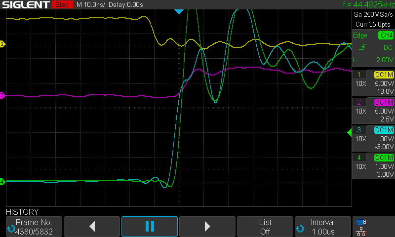
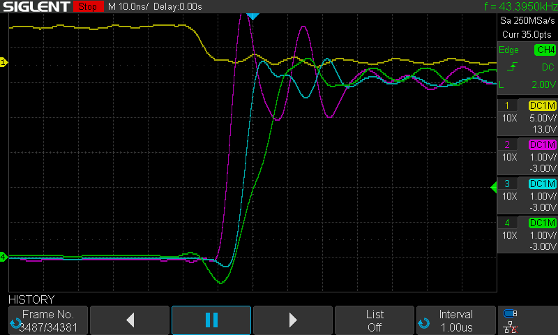
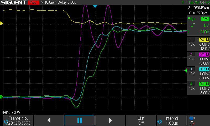
About this time, the 4-channel oscilloscope that I had ordered arrived. I was particularly interested in what was happening on A7 as it was a factor in the most instances of corruption. I started with looking at areas of the startup where we were writing to RAM and A7 transitioned from low to high. In the images below the clock signal is the yellow trace, the RAM chip select signal is purple, A7 is cyan, and the RAM write enable signal is green.
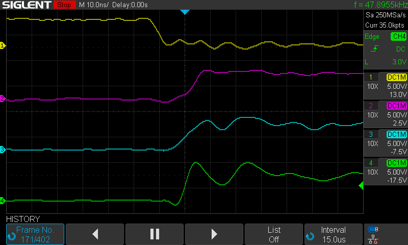
Zooming in we can clearly see that the A7 line transitions from low to high before the write enable signal transitions. This is important since I’m using the write enable signal to control the write to RAM (notice the RAM chip select signal rises after this).
I can’t verify that this particular signal resulted in memory corruption, but more often than not the A7 and write enable signals rose in tandem, which would be okay per the RAM’s timing specifications. Also, a quick browse through my oscilloscope’s history showed about as many of the above occurrences and I was seeing corrupted bytes of memory. Not conclusive proof, but very telling. It wouldn’t be too hard to write a program to confirm that the above was the cause of the problem, but I left it here.
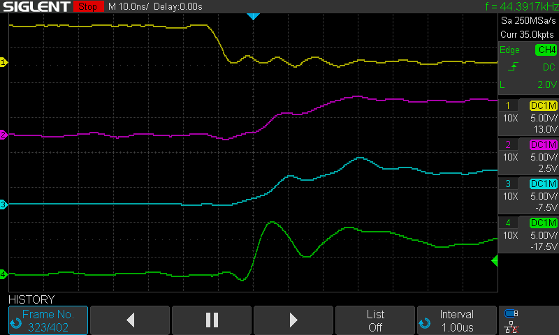
Running the same code for the build running with a 65C02 yielded the following traces.
And zoomed in
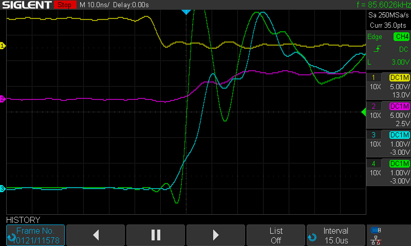
The A7 signal on Build 4 with the 65C02 rises much slower than that with the 65816. Thus no memory corruption. Remember, the only difference between these traces is that one has the 65C02 installed and the other has the 65816. The two chips have the same timing specification in this regard but the actual signal timing shows that there is more margin on the 65C02 than the 65816. Thus the build succeeds with the 65C02 but fails with the 65816.
Now remember that my 6502 Build 3 ran successfully with a 65816 installed. What’s the difference there? Three differences are clear:
- Build 4 uses a PLD address decoder while Build 3 uses discrete 74 series logic chips.
- Writes to RAM are controlled by the RAM write enable signal in Build 4 but the chip select signal in Build 3, and,
- The address and data buses are about a short as I could make them in Build 3 because this build was intended to test higher clock speeds and I tried to make everything as compact as possible. I followed a similar layout in Build 4 but wasn’t as tight with the bus wiring because it had caused some problems in Build 3 and wasn’t as easy to modify if needed.
Looking at the Build 3 traces, for the 65816:
And the 65C02:
Again, we see a somewhat slower rise for the A7 signal on the 65C02, but the RAM chip select signal is clearly occurring before it on both chips. This raises an interesting question; would a similar RAM write control scheme work on Build 4? I tried this unsuccessfully with a separate address decoding circuit in place of the Build 4 PLD (more on that in another post). Still to test though, reprogramming the PLD with this scheme.
Build 4 Status
So where does Build 4 stand? It appears to be running successfully with the 65815 and a 55 ns RAM. It also runs successfully with the 65C02, with both 12 ns and 55 ns RAM. I still want to do more work, within this build’s framework, to get the 65816 running with 12 ns RAM. Given that I don’t have room to add another chip, this probably will involve tighter address bus wiring or some change to the PLD.
I also haven’t tested banked ROM on the build yet. I still have so many things to investigate! Taking a line from an old boss of mine, “a busy employee is a happy employee”. I think it’s more true now that I’m my own boss than it was back then.